LA-4 Help Thread!

GroupDIY Audio Forum

Help Support GroupDIY Audio Forum:

This site may earn a commission from merchant affiliate links, including eBay, Amazon, and others.
Insomniaclown said:
I know that 2:1 ratio is much different than the others. I haven't done too much experimenting with it yet, but it sure does suck down the gain.

Yeah, same here. When I go from position 2 to 1 on the ratio switch my gain reduction hits hard. I have to back off the threshold quite a bit.

Looking at the compression graph in the manual this is completely normal as the soft knee means the Gain Reduction kicks in, slowly, way below the threshold.

Insomniaclown said:
This is my first hardware compressor, so I do need some time to get used to using it. I did some vocal recordings on it yesterday, and I loved how it sounded!

Damm Right!!! not my first hardware compressor, but my first "high caliber" compressor. Used to have "toys" such as the new Joe-Meek, Focucrite voicemaster and other "gizmos". When I first built and heard the LA4A I was blown away.... Especially nice on bass and vocals, whenever you need character.... now I'm selling all my other studio equipment so that I can build more DIY...

Insomniaclown said:
#2- My threshold control is super sensitive. A 1 mm movement results in massive GR. I have yet to adjust it with a test tone though, so this may be cleared up when I get to that.
Hey bro did you ever sort this out?

I have the same problem, I think it's because my pot is wired the other way round. I think on the original you have to turn the pot cw to lower the threshold. But I like it when you turn the switch ccw to lower the threshold and increase compression.

At the moment with my log pot wired the other way round (ccw for compression) I get, as insomniaclown says, a super sensitive threshold. Does this have something to do with the tracking of a log pot? as in the curve is steep at the ccw position?

If I want to keep the action of this pot the same (ccw for compression) but want smoother control, would a reverse log pot work better or maybe a linear pot will do?


3nity said:
Alirght i found those but they are 9mm not 10mm!!
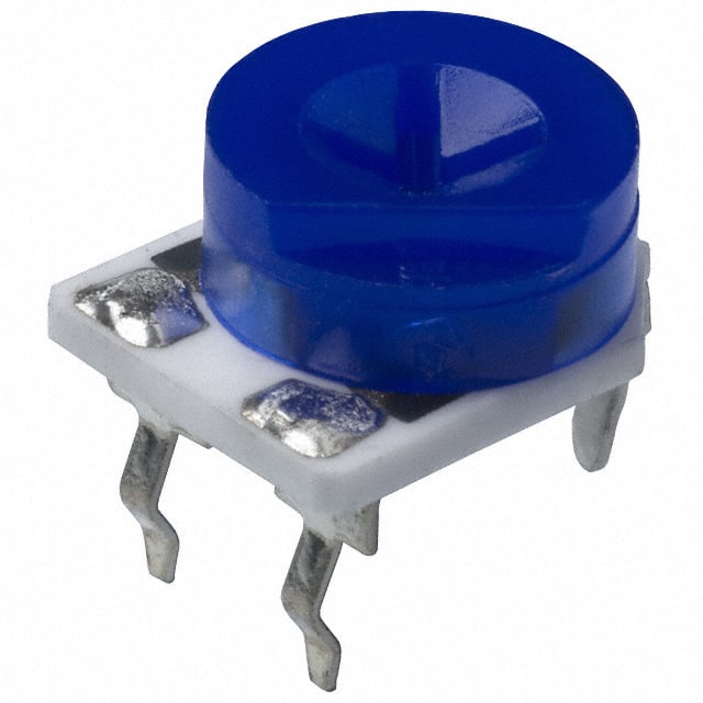
3309P%20SERIES.jpg

Any thoughts?

Hey, 3nity, I think does trimmers will do fine. Just stretch out the feet a little. That's what I did on mine...

J
 
Hello
Here's a little shot of my LA4a clone that I finished up today. I'm gonna change the knobs, but I think I'll stick with the hard core DIY front ;)
la4a.jpg
 
Matthew Jacobs said:
Yeah, same here. When I go from position 2 to 1 on the ratio switch my gain reduction hits hard. I have to back off the threshold quite a bit.

Looking at the compression graph in the manual this is completely normal as the soft knee means the Gain Reduction kicks in, slowly, way below the threshold.

I'll have to start experimenting with 2:1 next! Sounds like you can get some interesting sounds.

Matthew Jacobs said:
Damm Right!!! not my first hardware compressor, but my first "high caliber" compressor. Used to have "toys" such as the new Joe-Meek, Focucrite voicemaster and other "gizmos". When I first built and heard the LA4A I was blown away.... Especially nice on bass and vocals, whenever you need character.... now I'm selling all my other studio equipment so that I can build more DIY...

Yeah man! I was days away from throwing down on an ART pro VLA, but phrases like "good for the money" never sit right with me. I am glad I didn't go that route! Although, I would have been compressing things sooner, but it wouldn't have sounded this good!

Insomniaclown said:
#2- My threshold control is super sensitive. A 1 mm movement results in massive GR. I have yet to adjust it with a test tone though, so this may be cleared up when I get to that.
Matthew Jacobs said:
Hey bro did you ever sort this out?

I have the same problem, I think it's because my pot is wired the other way round. I think on the original you have to turn the pot cw to lower the threshold. But I like it when you turn the switch ccw to lower the threshold and increase compression.

At the moment with my log pot wired the other way round (ccw for compression) I get, as insomniaclown says, a super sensitive threshold. Does this have something to do with the tracking of a log pot? as in the curve is steep at the ccw position?

If I want to keep the action of this pot the same (ccw for compression) but want smoother control, would a reverse log pot work better or maybe a linear pot will do?

I have this sorted to a point. I also had my threshold control wired backwards, but by mistake. I didn't really get control of it until I had rewired all the controls by cutting off all the quick connectors and soldering the wires, and then running through the adjustment procedure. I have my threshold trimmer set quite high, which gives me more room to maneuver before compression begins. When the threshold does kick in it kicks in hard, but it is smoother then it was before. I like it!

My only remaining issue is the Ratio trimmer not adjusting anything. I just replaced it today, and there was no change. When I run the ratio test and increase the input by 20db, no matter what ratio I have set, the resulting output gain increase is the same. Just under 2 db. If I set to 1db of limiting at 4:1, and then select 8:1, the GR meter shows an increase in limiting. Same when I go 12:1 and 20:1, so I know the ratios are there. I think maybe my optos are too far out of spec with each other, so I am going to disconnect one and try again. Unless anyone else knows where I could look?

A different potentiometer could be good, although the Log taper is supposed to be quite subtle through its first 1/3 of rotation. If you like it backwards, a reverse log might be the way to go!

3nity- Those trimmers you are looking at are pretty much the same as what I used. They fit just fine!

Goldengeek- Bad ass looking LA 4 man!
 
The VTL5C4/2 would be used in place of using 2 optos. The centre leg is where the two LDR's are connected together. After checking out the schematic and the PCB layout, I would put the LED legs in Opto 1 (or 2, doesn't really matter). Put the centre leg of the LDR in the bottom soldering point of Opto 1, and then the 2 outside legs go to the top holes of Opto 1 and Opto 2. I could be wrong, but since the centre leg of the cell is where the 2 LDR's are connected, and the bottom holes on the Optos on the PCB are connected, it makes sense to me. Try it out and see what happens.
 
i bought vactrol vtl5c4/2 but i don't know how connect it!!!
have a look at page 28 of the la4a manual linked to in the first page of this thread for a diagram.

i was just about to ask the same question. ;)
 
Thanks mrclunk. I had it wrong. I should give that manual a thorough read.

I have done a bunch of work on yee old circuit trying to iron out a few issues, but I have a few more.

-Optos- retooled the chap stick tubes so that they fit nicely beside each other and not in a "V". Also replaced 5mm LED with 10mm LED. Also swapped one LDR for another that was a closer match.
- With the exception of the 4.99K/10K 1% resistors, and the resistors on the switches, all resistors are now 1/2 watt
- Replaced transistors
- Replaced 500 ohm ratio trimmer with a 1K
- Replaced all diodes. My overload LED works now. I had a 1n4004 instead of a 1n4740 for the Zener. Don't know why I did that. I also think I had 1n4740's where the 1n4003's were supposed to go. Silly me! I couldn't get 1n4003's, so instead I used 1n4004's which should be OK I hope. This is the last thing I did.

Before replacing the diodes- Clean sound, no overload LED, no discernible ratio difference except on 2:1, ratio trimmer not able adjust up to spec, stable meter

After diodes- Overload LED working, ratio trimmer still not adjusting up to spec, threshold control less sensitive and smoother. When gain reduction is taking place- ratio switch increase GR as ratio is increased but also increases distortion, and the needle on my meter is wavering back and forth a little bit as well. This wavering is when I set the unit into 1db of limiting using a 2Khz tone. It never used to do that.

EDIT: again. Got home last night, tried recording vocals and a different guitar. No distortion, clean transparent compression. Good times. I guess the battery in my other guitar was dying. I am going to try the ratio thing again, but using the NSL 32 setup described in the assembly notes.
 
thanks ihad found opto connection,but i have another question:

how to connecto oep transformer on a dual unit?
 
champ72 said:
thanks ihad found opto connection,but i have another question:

how to connecto oep transformer on a dual unit?

Don't you mean "transformers"? You need two transformers for a dual unit. (sorry is I miss read your question, but I'm assuming you are talking about 1 transformer)

J
 
Hate to say it man, look through the thread, It's only like 3 pages back

Luny Tune said:
benlindell said:
Hey Guys, just wanted to double check I'm doing a few things right.

1. I just want to leave this in the Low range, I just connect 2 and 3 correct?

2. For the OEP Transformer, to wire it as 1:1 I do what I did in the image?
Don't think you ever got an answer to this, did you?

1. Well, that depends...what do you mean by Low Range? I think the label on this switch is confusing. Once the switch is there you quickly learn what it does in which position. But to decide beforehand you must think of the switch as one that accommodates for level of the input signal. If the signal is high enough to overload the circuit, put it in "High" position. If the signal is too low for you to work with, put it in the "Low" position.

Now, for a constant "Low" position, just connect 2 and 3. For a constant "High" position just don't connect anything to 2 and 3.

2. I've connected the OEP A262A2E like this. The attatched picture is made from yours and is a bottom view. A is the tranny's original Primary side and B is the Secondary side. I use it backwards:

"To Transformer +" to B1
"To Transformer -" to B4
B1+2 is shorted
B3+4 is shorted

A4 to "From Transformer +"
A1 to "From Transformer -"
A2+3 is shorted.

Screen pin is connected to ground.
 
hello
Farnell has no bridge rectifier round (7278462)
can fit this (http://it.farnell.com/jsp/search/productdetail.jsp?SKU=9381430)?
Thanks
 
Just finished my dual LA-4 up today, sounds better each time I use it which is a good thing. still can't get the left channel to track perfectly but it's close. The inside is a rat's nest but it works, no complaints here, more pics here: http://blog.benlindell.com/?p=232

LA-4-2.jpg

LA-4-3.jpg
 
Yeah, this was my very first PCB layout and I had no idea it would result in such a messy wiring. ::)

But as you say, it works and once the lid is on you happily forget what's down there. :D

Nice job on the front panel!! ;D
 
benlindell said:
Just finished my dual LA-4 up today, sounds better each time I use it which is a good thing. still can't get the left channel to track perfectly but it's close. The inside is a rat's nest but it works, no complaints here, more pics here: http://blog.benlindell.com/?p=232

Thumbs up !

Don't worry, mine looks even worse  :) I wanted to use the case from an old D2MAC-reciever (with a new frontpanel)
and it is just big enough to squeeze everything in.

your front looks great by the way !
 
Looks really nice Bellindel.
Nice front panel!!! is it done by FPE?? i use a local laser engraver but he only does on black panels..
On the insides...
You can always re-twist the wiring or use heatshrink...
Well no matter how hard i try i always end up not liking my inside rack job.

The trick is to a send the wiring parallel to the board....

 
Thanks guys, I'm really happy with how it turned out too. I found an laser engraver in vermont that could take adobe illustrator files and also do black on clear as well as white on black.
 
They are recycled Sifam AL29s I got off ebay, pulled from an ADM, they are pretty burned in hence the color, of the 6 I got only 1 wasn't colored.
 

Latest posts

Back
Top