Low Ripple/Fast Settling AGC For Oscillator

GroupDIY Audio Forum

Help Support GroupDIY Audio Forum:

This site may earn a commission from merchant affiliate links, including eBay, Amazon, and others.
IC7 is high, which increases gain of IC3 for positive feedback.

Ah right, thanks. I was misleaded by the text which suggested me that turning on Q1 would cause negative feedback. Actually I think the text is just wrong--from page 7/8: When the FET resistance is low, the noninverting gain exceeds the inverting gain so that a noninverting overall characteristics results.

I don't follow these questions.

Mainly silly thinking from trying to make sense out of the misunderstanding.

I'll be back in a minute with the update schematic.

Samuel
 
Here we go: AGC_loop_r3.pdf

This adds the speedup-circuitry consisting of comparators U9/U10 plus JFET switches Q1/Q2. These are just conceptual drawings, a real implementation would likely add shunt switches for better offness, comparator hysteresis and gate overdrive protection.

I wonder if the speedup path for high oscillator output voltage case is necessary at all. At least the System One does not have it.

The multiplier output voltage note was wrong in revision 2, and revision 3 has a slightly higher nominal output voltage.

How does this look? Once this is approved by the experts I'll start drawing the prototype schematic.

Samuel
 
Samuel Groner said:
IC7 is high, which increases gain of IC3 for positive feedback.

Ah right, thanks. I was misleaded by the text which suggested me that turning on Q1 would cause negative feedback. Actually I think the text is just wrong--from page 7/8: When the FET resistance is low, the noninverting gain exceeds the inverting gain so that a noninverting overall characteristics results.

The quote you excerpted in italics is correct...  The inverting gain of that stage is fixed, but the non-inverting gain varies, and increases as FET resistance drops, so can change from net inverting for negative feedback when FET high Z, to non-inverting for positive feedback when FET is low Z.

So you are correct, turning on Q1 causes positive feedback...

I'll be back in a minute with the update schematic.

Samuel


I'm not smart enough to look at that schematic and predict how it will work, but I am nervous about it calmly converging on a stable level without overshooting or hunting between modes. My gut feeling is fast mode is too much feedback, so the AGC loop will toggle between the two, and not cleanly converge.

Ideally you want to speed up the charging rate of C3, along the lines of what the diodes are already doing.

I did some dynamics, side chain designs where a similar smoothing cap could vary between fast time constants for large changes returning to slow time constants for small errors. 

Other speed up tricks to consider:

#1 a resistor in series with C3 that you could shunt with a JFET when stable.

#2 if the resistor in series with C3 is on the opamp - input side, a clamp diode to ground at that node between R and C3 could quickly charge discharge C3 for steps larger than a diode drop (across added R).


I don't have good experiences with dual rate AGC loops, so take my advice with a grain of salt...  that last time I tried was back in the '80s on the TS-1. I ended up tolerating around .15% THD to enjoy an adequately fast settling time characteristic. My Osc went from 30 kHz to below 20 Hz in one swept range so agc loop was working a bunch.

JR
 
Must have been a bad day yesterday to ponder AGC loop polarities... Thanks for the repetitive corrections.

My gut feeling is fast mode is too much feedback, so the AGC loop will toggle between the two, and not cleanly converge.

Not unlikely. I'm prepared to increase R12/R13.

Ideally you want to speed up the charging rate of C3, along the lines of what the diodes are already doing.

With D1/D2 active the integration time constant is just above 6 ms, so perhaps not even that limiting for my needs (settling in 1 s would be acceptable). I was thinking of shunting R21 while the speed-up is active, but this is essentially the same thing as the diodes do. But thanks for the suggestions, will keep them ready if it does not work as expected.

Samuel
 
Finally I got around testing a prototype. I'm very pleased with the results; second and third harmonic are at or below -130 dB for 1 kHz and all higher order harmonics below -155 dB if measured with an Audio Precision SYS-2722. THD+N reads -119.3 dBu (0.00011%) in a 22 kHz BW. This is several dBs less than with the SYS-2722 generator, so we're definitely heading somewhere. And that's just with LT1468 opamps--wait till I throw in my secrete discrete recipe ;).

The speed-up circuitry does its job extremely well--what have been settling times of minutes without are now seconds. There remains however some low-level settling indicating that the basic AGC loop has underdamped response. I hope that I can further reduce this by lowering the thresholds of the speed-up comparators. But perhaps there is also a trick regarding the time constant of the integrator; I've found an IEEE paper discussing the stability of such leveling loops and suggesting the introduction of a zero; will need to read in more detail. Any other insight appreciated.

Samuel
 
Congrats that is very respectable and fast for a low distortion loop...

Are you taking your final output from the LP output of the SVF? 

If yes it might be interesting to look at purity and noise floor of BP output?

JR

 
Are you taking your final output from the LP output of the SVF?

Yes.

If yes it might be interesting to look at purity and noise floor of BP output?

I'll do that once the settling behaviour has become decent. Some more tests indicated that at 10 kHz and 100 kHz settling is considerably worse, will need to look into this.

Samuel
 
Yes, the behaviour is strange. I think it has to do with some side effects (whichever nature) which make the oscillator oscillate (at the correct frequency) in the highest frequency range (100 kHz) even without leveling loop attached; so the leveling loop has to work hard to get the amplitude down. Any idea what could cause such behaviour? I guess it must be some circuit strays (or opamp phase shift) which by accident make the Q of the filter near-infinite. Perhaps I'll have to increase capacitor losses by means of a parallel resistor...

In the 100 Hz range the settling is slower than in the 1 kHz too, so this is consistent with theory and your observations.

The IEEE paper is only of partial help; they assume that the oscillator frequency is low (1 kHz) and the variable gain element has a constant (i.e. independent of control voltage) gain constant. Without these assumption the problem appears to be very difficult to treat analytically, but unfortunately both are just weakly fulfilled in this particular case.

Samuel
 
At very high frequency you may be seeing some impact from finite gain bandwidth product of typical opamps. Also the typical one pole internal stability compensation may be introducing phase shift to the response within your passband. If this phase shift is significant it might interfere with the trig identity (or not). The phase response should be well defined by the feedback network "as long as there is adequate loop gain margin".

I don't know if this is useful, and never quite wrapped my head around the theory, there was a thread about a year or two ago with opamps nested inside another opamps feedback loop, that might provide more than enough gain. IIRC that topology was also associated with a low distortion oscillator.

Obviously with a DOA you can explore alternate or simply higher frequency stability compensation poles, while this is pure speculation. The rouge waveform behavior will hopefully provide evidence leading to the actual problem.

Good luck,

JR
 
It seems as most problems are solved now. Settling at low frequencies was improved by a zero in the integrator and some increased gain in the AGC loop and is now about a second at 100 Hz, and less above. The settling instability in the 100 kHz range was not any opamp limitation but rather the speedup comparators were switching off too slowly. But the speedup is anyway not needed in this range, as settling is fast enough without. The oscillator is now tested from 3 Hz to 300 kHz; the two trim pots (one to sum the squared signals and one to pre-trim filter Q) definitely need adjustment for the different frequency ranges.

2nd and 3rd harmonic are below -130 dB even at the inverter output for 10 Hz to 10 kHz; at 100 kHz the SYS-2722 is a serious limitator but with some tricks I got to see a THD residual at -105 dB. Amplitude flatness is 0.05 dB from 3 Hz to 10 kHz and 0.28 dB to 300 kHz; the later might include some considerable measurement error from the SYS-2722.

Samuel
 
Great...

I'm still curious to see differences if any between BP and LP outputs. May be a tradeoff between noise and THD. but no hurry it can wait while you pursue other improvements.

Back in the day on my much lower performance bench I ran my THD analyzer at -10dB below nominal and fed the product output to a separate spectrum analyzer to work around the nonlinearity of my analyzer's notch filter.  Of course to look for distortion products, not noise floor. You may be approaching residuals of even decent bench equipment audio paths, so this is of limited utility.

I guess we should wait until you hot rod the opamps. I would be tempted to review the contribution from the multiplier you use for positive feedback? Perhaps  tweaking the levels around the multiplier before or after. You could also replace it with a modern high performance VCA suitably scaled to reduce it's error contribution. 

If the nonlinearity is dominated by the control voltage ripple then this won't matter.

good job.


JR

PS: In case I haven't mentioned this before you might improve your overall level tracking accuracy by cap coupling one of the two quadrature outputs in the AGC loop. This way you will still get the AC ripple cancellation, but gain control will respond to the DC content of only the one bandpass you are using for your output.  This may end up trading level accuracy for LF distortion so pick your poison.
 
I'm still curious to see differences if any between BP and LP outputs. May be a tradeoff between noise and THD.

I cannot see any difference regarding THD+N (400 Hz to 80 kHz BW) or THD for BP and LP output at 1 kHz or 10 kHz oscillator frequency as the SYS-2722 appears to dominate the reading. The HP output shows--depending on oscillator frequency--three to five dB higher THD+N (that is, more +N). With a 10 Hz to 22 kHz BW I can squeeze out one dB better THD+N for the BP.

If the noise floor is measured with the oscillator forced to zero level (by injecting a voltage into the AGC loop) one can see the noise differences. When I get home I'll upload a pic.

Back in the day on my much lower performance bench I ran my THD analyzer at -10dB below nominal and fed the product output to a separate spectrum analyzer to work around the nonlinearity of my analyzer's notch filter.

I do this as well, but there seem to be some effects which increase distortion at some point again. Not sure what this is, but the System One showed the same effects allready.

I would be tempted to review the contribution from the multiplier you use for positive feedback? Perhaps tweaking the levels around the multiplier before or after. You could also replace it with a modern high performance VCA suitably scaled to reduce it's error contribution.

I do consider the use of a VCA; this is advantageous as--apart from the probably allready lower THD--the dominant harmonic is often the 3rd, while for the optoresistors it is the 2nd. And the 3rd will get more LP-filtering.

If the nonlinearity is dominated by the control voltage ripple then this won't matter.

I don't think it is--the ripple can be trimmed to 20 mVp, which is quite low I'd say. With 100 mV however I can measure a slight increase in THD.

You might improve your overall level tracking accuracy by cap coupling one of the two quadrature outputs in the AGC loop.

Thanks, will consider that.

Samuel
 
So here's the FFT with the noise floor from the three outputs: oscillator_noise_mute_1kHz.png

BTW, I've found a discrete square law amplifier schematic in the OP297 datasheet (page 12). As I've noticed that the multiplier ICs are quite noisy (the wideband noise is about as large as the residual sinusoidal error voltage) I hope to be able to improve upon this with a discrete implementation. Otherwise I will at least need to operate the multiplier at their upper dynamic range limit, but again this increases residual sinusoidal error voltage.

Both the AP System One oscillator and the HP 8903A use sample-and-hold stages to get a ripple free amplitude signal. This would be another entirely different, but not unpromising approach.

Samuel
 
> for the optoresistors it is the 2nd

Should be Third. Unless there is DC across them (I have not followed the story-line).
 
Samuel Groner said:
So here's the FFT with the noise floor from the three outputs: oscillator_noise_mute_1kHz.png
I assume yellow is the BP trace?
BTW, I've found a discrete square law amplifier schematic in the OP297 datasheet (page 12).
I'n not sure that's apples and apples... the data sheet link looks like typical log square/square root circuits that accept DC or rectified AC, not AC.

If you look at the schematic I posted in this thread about a year and a half ago you will see full wave rectifiers in front of similar log math circuitry.


As I've noticed that the multiplier ICs are quite noisy (the wideband noise is about as large as the residual sinusoidal error voltage) I hope to be able to improve upon this with a discrete implementation. Otherwise I will at least need to operate the multiplier at their upper dynamic range limit, but again this increases residual sinusoidal error voltage.

Isn't the noise of the multipliers on the sin/cos outputs filtered by the agc loop RxC?

VCAs are quiet but log gain control input is inconvenient to make simple  X x Y multiplier.  Perhaps OTA or similar gain cells with linear gain control would be better to square audio signals.  Perhaps some variant on 1496/1596 mod/demod using dsicretes.

Both the AP System One oscillator and the HP 8903A use sample-and-hold stages to get a ripple free amplitude signal. This would be another entirely different, but not unpromising approach.

Samuel

I need to think about this.. it seems a simple S & H will overshoot and hunt back and forth around stable value. I'm sure they resolved that.  I guess the combination of the speedup circuit with S & H might prevent overshoot between updates.

JR
 
Should be Third.

That's what I've told them as well, but the measurements clearly indicate second as main problem.

The data sheet link looks like typical log square/square root circuits that accept DC or rectified AC, not AC.

Yes, but I thought that I can get around this by level shifting the input. Perhaps this is not well thought through yet though.

Isn't the noise of the multipliers on the sin/cos outputs filtered by the AGC loop RxC?

The problem is that for fast settling the zero of the integrator needs to be low in frequency--in fact so low that the integrator gain never falls below unity. This prevents filtering.

It seems a simple S & H will overshoot and hunt back and forth around stable value.

It's a two-stage design; first stage tracks one quarter of the sine, the second samples this value during the remaining cycle. See 1980-08.pdf, page 11 or the System One service manual from the AP page.

Samuel
 
re: level shifting before log squaring circuit. The trig identity relies upon -N x -N =+N^2. If you offset the whole thing positive by one, you get 1.7^2 during positive swing but .3^2 during negative swings, not exactly ripple free..
======

Thanks for the link... that 8903 schematic certainly isn't literal but interesting concept.

If we assume good waveform integrity, managing the peak level should be just as accurate as average level.

I like the idea of two stage, but rather than track and hold followed by a sample and hold, I'd use a peak hold, then latch that to a sample and hold at the zero crossings. Using full wave rectification the hold could be updated at every zero crossing. After latching the peak, partially discharge the former held peak to set it up to accurately capture the next peak. This partial discharge needs to be a one shot rather than small continuous drain to not cause error with frequency.  Any DC error in the sine wave will cause a step in the control voltage at the osc fundamental, so perhaps half wave rectification will be cleaner.

This should give both a relatively quick response and low ripple. The peak hold cap needs to be low leakage and low DA and use low input current buffers, but modern opamps could surely handle.  The DA can be ignored if per cycle discharge is modest and peak cap is not moving around much between cycles.

JR
 
Not exactly ripple free.

Too bad... Looks like I need to consider the S & H stuff if I don't become happy with the multipliers. I noticed that the amplitude (perhaps also phase?) appears to be noisy--at least when viewed on a digital oscilloscope, and at the moment I attribute this to the multiplier noise. Although flatness and ripple is pretty good for this approach, I'm somewhat concerned about this behaviour.

That 8903 schematic certainly isn't literal but interesting concept.

Full service manual is downloadable from the Agilent site.

Samuel
 
I assume yellow is the BP trace?

Forgot to answer that one before: yes.

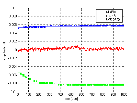
Some more research on amplitude stability:

amplitude_stability.png


This shows the amplitude (at 1 kHz) measured over a time of 1k seconds for my oscillator adjusted to +4 dBu and +14 dBu (which operates the multipliers at +10 Vp) as well as the SYS-2722 generator. Surprisingly the later shows highest drift, but is obviously less noisy than the multiplier AGC loop at +4 dBu. While operation at +14 dBu is sufficient to make the multiplier noise neglible the nonlinearity of the multipliers results in untrimmable ripple residual, which is no acceptable for the particular application. There are multipliers from ADI with lower errors, same noise and horrifying prices (about 100$ each!), but the improvement is probably not drastic.

Samuel
 

Latest posts

Back
Top