Low Ripple/Fast Settling AGC For Oscillator

GroupDIY Audio Forum

Help Support GroupDIY Audio Forum:

This site may earn a commission from merchant affiliate links, including eBay, Amazon, and others.
Yes perhaps the limits are a bit optimistic. As long as the errors are monotonic (i.e. do not jump e.g. with range switching) it should be possible to find suitable RC corrections; but there are errors which definitely are not monotonic, the one from DC offset I mentioned is an example. But as long as I don't have a precision meter at 300 kHz there is anyway not much to be done about flatness.

In any case next step is to derive a promising peak hold/sample-and-hold combo and test it. I'm also waiting for a discrete multiplier board to arrive which should replace the opto resistors (for the amplitude/Q control).

Samuel
 
Some investigation of discrete comparators showed that indeed it would be rather simple to derive a scheme for a suitable precise track-and-hold amplifier. The use of such is advantageous over a peak detector because it is easier to design for wide bandwidth and because hold step compensation may be applied. So at the moment I do follow this route.

One particular problem I encountered is the design of the (non-retriggerable) monostable multivibrator which defines the the time span where the track-and-hold amplifier (first stage) is in hold mode and the following sample-and-hold amplifier samples. To allow sufficient time for tracking in the first stage there should be some defined time period (10-20 us) where the multivibrator remains low (i.e. track-and-hold amplifier tracks and sample-and-hold amplifier holds) after it has been triggered for 100 us high, even if at high frequencies the signal would trigger earlier for low. Any idea how this is most easily done? I guess I could use two timers (or dedicated multivibrator chips) and some logic, but perhaps there is a solution with just one timer?

Samuel
 
Short delays were commonly done with CMOS gates and a simple RxC. Very short delays could use propagation delay of one or more gates in series. (Don't use the old 555, pretty nasty part).

I'm not sure I even see how to properly apply a track and hold. When do you gate it off? It seems controlling that would be a major accuracy concern.

If we only use the peak detection when it is X percent above or below target, it's errors or cycle to cycle noise are not significant.

JR
 
When do you gate it off? It seems controlling that would be a major accuracy concern.

The zero crossing of the 90° output is at the peak of the 0° output. I've posted a graph showing the effects of aperture delay a couple of post above--we need something below 100 ns, but that's feasible.

What's wrong with the 555? Never cared much about logic before.

Samuel
 
OK, now that makes sense. I didn't see that you were using quadrature to define peak. Delay past peak will cause error that changes with frequency so needs to be zero.

Perhaps use a track and hold that turns on slightly before, then off hard at zero. So high speed only needed in one direction. (Note: with peak hold, timing accuracy is not an error source, while there may be other errors.)

My caution about the 555 is that the original part is crude and notorious for putting current spikes in the power supply. IIRC there are newer improved versions that are cleaner. Not really logic, but glue circuitry around this needs to be quiet.. First do no harm.

JR
 
Perhaps use a track and hold that turns on slightly before, then off hard at zero.

That's asking for a delay line--hard work (at least for someone used to frequencies from 20 Hz to 20 kHz)...

It looks like something like the HCF4098B would be a more clever solution than the 555. Same wide supply range up to 20 V (helpful for driving the JFETs directly) and input/output available in both polarities. One monostable is then set for 100 us hold and the other to say 110 us; first monostable drives the switches and second an AND gate at the input of both monostables. This should guarantee a 10 us low time after a 100 us high, right?

Samuel
 
Samuel Groner said:
Perhaps use a track and hold that turns on slightly before, then off hard at zero.

That's asking for a delay line--hard work (at least for someone used to frequencies from 20 Hz to 20 kHz)...

It looks like something like the HCF4098B would be a more clever solution than the 555. Same wide supply range up to 20 V (helpful for driving the JFETs directly) and input/output available in both polarities. One monostable is then set for 100 us hold and the other to say 110 us; first monostable drives the switches and second an AND gate at the input of both monostables. This should guarantee a 10 us low time after a 100 us high, right?

Samuel

I guess I am still not following.

If you want to use a track and hold to capture the peak of your wave form, you want to turn it on some finite time ahead of the peak to begin tracking, and then sharply turn it off at exactly the peak.  The amount of time leading the peak will not cause a peak error but will increase ripple on that track and hold output, which could be removed by a second hold stage that latches this stable peak into another hold circuit after capture.

To anticipate the quadrature zero crossing just offset the comparator some fractional voltage before zero.  The speed of this comparator turning on before is not important but turning off at zero is the main error term wrt frequency, if using the two stage hold.

Sorry I am not familiar with IC one shots.. it's so simple to make them with a couple transistors or gates, I've never used one. Probably used in some other high speed disciplines that I didn't dabble in. Nowadays with digital systems running at many MHz it's easier to generate accurate small delays by counting clock ticks. 

JR

PS: and a peak hold instead of a track and hold wouldn't require precise timing., albeit having other considerations.
 
To anticipate the quadrature zero crossing just offset the comparator some fractional voltage before zero.

An offset works just for one frequency. At frequencies lower than that the hold will be too earily, and at higher frequencies too late.

Samuel
 
I don't think we disagree that much, just not talking about the same thing. There are three events which need to be timed:

* start of first stage track mode; somewhere before peak amplitude; uncritical, easily solved and (from my side) not part of the discussion
* end of first stage track mode (and start of second stage sample mode); exactly at peak amplitude; very critical, but not actually what I want to discuss as presumably solved with discrete precision/high-speed comparator
* end of second stage sample mode; fixed time (I assume ~100 us) after peak amplitude/first stage hold start/second stage sample start; not very critical, but what I'm talking about

The one shot is used to derive the ~100 us time span. Now the problem is that for certain frequencies with a period at or slightly above 100 us there might immediately follow another peak, which makes the one shot go high again before the first stage had enough time to track the input signal to a sufficient degree. So the output of the one shot should remain low for say 10 us, and that's the problem I'm considering at the moment.

Samuel
 
Just like you use quadrature timing to define peak by a phase offset output zero cross, the zero cross from the BP output could likewise define a fractional wavelength time duration past it's peak. Acquisition time at steady state should not be problematic since voltage being latched should be pretty much the same voltage as is already being held. For large changes this will probably not be the limiting factor for settling time. making this too fast could actually increase hunting.

I agree that the timing error of the track to sample hand off can be made small. Even IC comparators are generally pretty fast in at least one direction, and the sine wave is at the slowest changing part of it's waveform.

Different strokes..  I would try to keep this simple, and use this only for a large error fast loop. Using a slow average detector for the after settled loop, would make errors in this fast loop only present during transitional settling.

JR
 
Just like you use quadrature timing to define peak by a phase offset output zero cross, the zero cross from the BP output could likewise define a fractional wavelength time duration past it's peak.

The key point is that for the second sample-and hold stage we want a fixed track time, not something dependent on oscillator frequency. This greatly relaxes the droop requirements of the first stage, i.e. a small capacitor can be used. This in turn gives the high bandwidth which is required for amplitude flatness.

The new level detector based on the two-stage track-and-hold/sample-and-hold approach is working, although not yet tested within the AGC loop. I could spend hours watching the nice staircase waveforms when sampling triangles and sines.

Samuel
 
Without seeing a schematic I may not be visualizing the problem the same way you are.  Working backwards from the desired result we have a hold buffer that continuously tracks the output sample cap.  This output sample and hold gets updated once(?) per cycle with the output of a track and hold that captures the peak amplitude per cycle. The timing of the output sample and hold acquisition is probably not very critical as long as track and hold is finished and stable, and acquisition time is adequate for a stable result. This could be as simple as shunting two caps to each other without active buffering.  The track and hold which is doing that actual peak level acquisition has two timing events. Start to track, and stop tracking to hold. The stop tracking and hold, should be precisely at peak perhaps as defined by quadrature zero crossing. At very high frequency, propagation delay in this circuitry could create a frequency dependent error.  The start time of this track and hold circuit is not important in theory, but in practice using a constant time window vs, constant phase window means the track will be starting from a different voltage at different frequencies.

If using low DA caps this is probably not a big deal, and even marginal acquisition time will just take a few extra cycles to settle after a larger step change. 

While we seem to be of different minds regarding constant time or constant phase offset one could generate phase offset by summing two 90' outputs with different weighting (50-50 weighting would give 45' phase shift ).

or not...

JR


I forget where you are at, but had a deranged thought which may apply.

You want a fixed amplitude, OK. But you MUST have stable oscillation.

And to be stable the gain must be exactly 1.00000000....

So catch a peak on C1, hold it on C2, catch the next peak, compare for equality.

Equality can be sensed by dumping C1 to C2 and sensing current. If zero, then gain -is- 1.0000..., if current flows the direction and magnitude suggest how gain must be changed.

Yes, gain can be stable at any amplitude, so you need a second loop comparing against 5.00V peak or whatever you want. This would be used to "lean" the gain=1.000... loop to allow gain to rise then fall to arrive at the desired amplitude.
 
Just a quick update on this project: the track-and-hold/sample-and-hold approach is working extremely well. The residual on the output is about 2.5 mVpp--most of that is just noise, there's almost no correlated signal. Definitely the way to go--that's something like two orders of magnitude better than the trigonometric approach.

Samuel
 
I don't recall where you are on this.

It's a huge project, must have spent several hundred hours on it now. Design of the AGC loop, evaluation of passives regarding distortion (nothing trivial at -140 dB), development of discrete opamps etc.

If that approach gives both quick settling time and low/no ripple, that is a good thing.

It does. With the speed-up circuitry deactivated a 100 Hz sine settles (visually on the scope) within 1-2 s. Will try with the speed-up thingy tomorrow.

Samuel
 
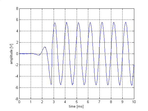
Here's the settling characteristics at 1 kHz:

settling_1kHz.png


Pretty decent I'd say. Still struggling somewhat with frequencies above 100 kHz though, the AGC loop tends to be unstable up there.

Samuel
 
That's remarkable. I assume there's no LF gain hunting if you go to a wider display time scale.

At 100kHz can you perhaps back off some of the speed up stuff since you should have naturally faster settling at the HF?

JR
 
I assume there's no LF gain hunting if you go to a wider display time scale.

It's hard to tell from the low-res digital scope I have at hand but I'd say there's nothing. The output of the AGC integrator settles within 40 ms to a fixed DC value which is another strong indicator. In fact shaping the loop response ain't that difficult at all once you got the trick; it can be shown that the gain above the integrator zero needs to be 1/(pi * Vp) where Vp denotes the peak voltage of the sine. This makes the AGC loop adjust the multiplier to a value where the amplitude reaches the desired value within exactly one cycle. As the track-and-hold/peak-and-hold amp puts out a new value once every cycle the next error voltage will be zero.

Samuel
 
Back
Top