Low Ripple/Fast Settling AGC For Oscillator

GroupDIY Audio Forum

Help Support GroupDIY Audio Forum:

This site may earn a commission from merchant affiliate links, including eBay, Amazon, and others.
Thanks.. yes yellow was an easy guess looking at the frequency response of the noise floor.

Amplitude stability vs. frequency will be a harder test.. amplitude stability vs time will be temperature stability as much as noise (my guess).

I am leaning toward investigating the sample and hold approach for the control loop...  but perhaps add some non-linear filtering after the S&H

1- grab peak amplitude for 1/2 cycle
2- latch that into a hold.
3- filter that held voltage with long time constant
4- speed up path if control voltage delta is more than X amount for faster settling.

Seems simpler and lower noise than trig identity with multipliers.

JR

PS; For $100 you can surely roll your own low noise multipliers.
 
What I don't quite understand is the noise specification of the AD633; they clearly specify output noise as 1 mVrms (5 MHz BW). What I see on the scope is surely one order of magnitude higher. Any idea..?

Amplitude stability vs. frequency will be a harder test.

I've used the RMS function of a digital scope two days ago as presumably it has pretty flat response, although absolute accuracy ain't promising. My HP 3400A thermal RMS meter appears to have some minor peaks and dips in the frequency response, but basically I think a thermal meter would be a clever choice as well. I'd like to have a HP 3458A though, its sampling AC measurements are hard to beat.

I am leaning toward investigating the sample and hold approach for the control loop.

Me too, allready studying S & H amplifier topologies. One particularly promising thing is that one can subtract the reference voltage and amplify the error voltage ahead of the S & H stages, thereby proportionally reducing the ripple resulting from S & H errors. Another intriguing possibility is a differential S & H path--given enough luck in error matching they will become common-mode and cancel.

Samuel
 
No idea on mult noise.
-----
Yup, when you approach and/or get better than bench performance, "who can you trust"?
-----
For S & H the issues seem pretty basic. Low input bias and offset current in buffer stage. DA of capacitor can be an issue if large voltage changes but presumably if sample to sample change is small, so DA probably not important. Capacitor leakage is likewise an error term, but most film caps probably OK. Polystyrene was a a popular S & H cap (for low DA, etc).

Finally the switch not only needs low on impedance and high off impedance, but low charge injection from turn on/off waveforms.

Using CMOS transfer gates can't be easily slowed down, but the gate charge injection should be roughly constant so perhaps a non issue. A JFET switch could be slowed down to mitigate charge.

Using a two stage (peak hold, followed by sample and hold) approach might allow very slow, perhaps sine wave, switch waveforms  (using  JFET switches). Keeping digital waveform out of the box might be useful.

JR

 
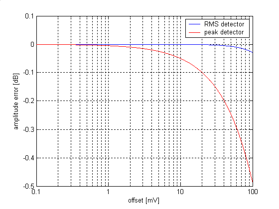
Some research on sample-and hold amplitude stabilisation; first peak level detection is much more sensitive to DC offset than true RMS. While static offset is easily trimmed, there might be some influence on frequency flatness as bias currents of the integrator amplifiers see different resistances when frequency switching. Here's a plot showing the resulting amplitude error for a +4 dBu oscillator level:

offset_error.png


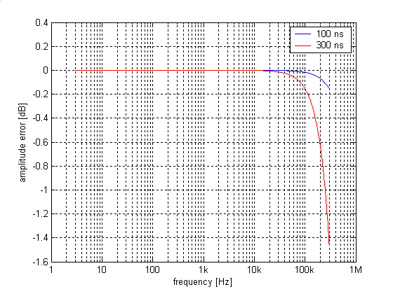
Second aperture delay (closing switch) in the first sample-and-hold stage results in amplitude underestimate, and more so at high frequencies. Shown here the errors for 100 ns and 300 ns delay:

aperture_error_100ns_300ns.png


I'm not quite sure what delays to expect from standard comparators but 300 ns seems to be rather fast already, right?

The use of a peak detector instead of the first sample-and-hold stage seems to be a possibility to reduce this error; the main limit probably being diode switch-off. However, there is little literature around for peak detectors suitable up to 300 kHz with high precision and low noise. I have a simulation running which uses an inverting peak detector with 20 dB gain; subtraction of the reference voltage is conveniently done in the same stage. This seems to achieve an amplitude flatness within about 0.05 dB from 3 Hz to 300 kHz, which ain't bad but needs very high-speed opamps. Any other idea?

Samuel
 
Samuel Groner said:
I'm not quite sure what delays to expect from standard comparators but 300 ns seems to be rather fast already, right?

Hardly. Something as ancient as the LM339 is specced for 300ns typ, given enough input overdrive. Modern comparators are much much faster. I regularly use the LT1720 which comes in SO-8, requires some care to layout and has a propagation delay of 4.5ns for a few tens of mV input difference. That part has hysteresis, which may not be what you want here.

Linear shows DIP comparators switching at up (down?) to 10ns. As always, newer faster parts run on reduced rails (and thus have reduced input CM range).

Samuel Groner said:
The use of a peak detector instead of the first sample-and-hold stage seems to be a possibility to reduce this error; the main limit probably being diode switch-off. However, there is little literature around for peak detectors suitable up to 300 kHz with high precision and low noise.

What would you consider high precision/low noise? A peak detector with a fast comparator and a Schottky diode should work fine for your purposes (as far as I can see) up to several MHz. Then again, a fast comparator will have more BW and this more noise.

JDB.

 
Thanks; I've seen the LT1720, but I need something which swings down to about -15 V to switch the JFETs off. I could add a discrete stage, but then this will again add delay. Any suggestions?

What would you consider high precision/low noise?

Ideally 0.1% precision and 1 mV wideband noise.

A peak detector with a fast comparator and a Schottky diode should work fine for your purposes (as far as I can see) up to several MHz. Then again, a fast comparator will have more BW and this more noise.

Any link to a schematic? All reasonably precise comparator-based peak detectors I've seen had a hefty low-pass filter at the output which is a no-go for loop stability.

Samuel
 
Samuel Groner said:
Thanks; I've seen the LT1720, but I need something which swings down to about -15 V to switch the JFETs off. I could add a discrete stage, but then this will again add delay. Any suggestions?

Very few fast comparators have large output swings (mostly because slewing gets in the way). If you don't need much better than a few tens of ns I would look at a discrete stage (which might be as simple as a PNP grounded base stage, depending on what kind of swing your JFET sees). Or a comparator with one of those nifty DSL driver chips as level shifter.

How fast can your JFETs switch anyway?

Samuel Groner said:
What would you consider high precision/low noise?

Ideally 0.1% precision and 1 mV wideband noise.

That should not be too hard, especially with the usual trick of two diodes in series with their midpoint bootstrapped to reduce leakage currents (which would otherwise kill you at low frequencies).

Samuel Groner said:
A peak detector with a fast comparator and a Schottky diode should work fine for your purposes (as far as I can see) up to several MHz. Then again, a fast comparator will have more BW and this more noise.

Any link to a schematic?

I was afraid you'd ask. We had a few but they all went away when Wayne (mediatechnology) left. This:

Comparator_Peak_Detector_NPN_Boost.jpg


is one, but not exactly what I had in mind. This one uses ECL to do its thing. I think you get the picture, if not I'll see if I have an old known-working design (or I'll draw the general idea).

Samuel Groner said:
All reasonably precise comparator-based peak detectors I've seen had a hefty low-pass filter at the output which is a no-go for loop stability.

That's really only necessary if your signal envelope is rapidly changing. For your oscillator AGC that shouldn't be an issue. Of course, any peak detector needs to have some non-infinite time constant to be useful inside a control loop. This will necessarily generate some ripple for a constant signal.

JDB.
[my instinct would be to throw a microcontroller with a non-linear control loop at the problem, but that probably says more about my mindset than about what the optimum solution is]
 
This may be drug-induced (I tore my back), but:

IF the sine is very good (your goal), then slew-rate at zero-cross is a measure of amplitude. And should have low DC sensitivity. And happens a 1/4 cycle ahead of (also behind) the peak.

No, I don't have any instant-idea for rapid precise slew-measurement.

You may be head-banging a macro version of Heisenberg Uncertainty. The better you know one thing, the less you know another. The product of accuracy and speed may either be limiting, or at least exponentially expensive.

I suppose 6-phase ocillator is not practical? 6 R-C sections working at 30 degree phase-shift each, plus their inversions, gives a "peak" every 15 degrees. In mega-DC power applications, low ripple without filtering. In this case, no 180 deg wait, and you could maybe sum/average/vote the 12 peaks to reduce errors.

Off-topic: calculators do not last as long as slide-rules. My 7 year old TI 30Xa went stupid. My 45+ year old slide-rule still works fine for resistor-ratios, but pretty terrible for adding-up purchase-orders. The interesting news is that the new improved 30Xa has the keys in the same place BUT has bigger display. Hmmmm. Are they suggesting my eyes are getting older? That half the reason I wear bifocals is to glim the calc?
 
Thanks for the further responses.

We had a few but they all went away when Wayne (mediatechnology) left.

I think these might still be availbale here: www.picocompressorforum.com/forum/php/viewtopic.php?f=6&t=111

That should not be too hard, especially with the usual trick of two diodes in series with their midpoint bootstrapped to reduce leakage currents (which would otherwise kill you at low frequencies).

Here's one which uses a comparator: www.edn.com/article/CA421510.html

However the errors are clearly larger than what I hope to achieve. Some more circuits:

* http://cds.linear.com/docs/Design%20Note/dn61.pdf standard approach with fast opamps--10% error at 300 kHz.
* www.linear.com/ltmagazine/LTMag_V06N2_May96.pdf page 22ff, interesting but probably not the best way for this problem.
* www.analog.com/static/imported-files/data_sheets/PKD01.pdf not particularly precise but interesting topology; could perhaps be enhanced with a discrete implementation.
* www.analog.com/static/imported-files/data_sheets/AD8033_8034.pdf goes into more detail about dynamic error reduction.

BTW, leakage currents from the diodes/opamp/switch are not that much of a problem, as the voltage needs to be accurate to just 100 us till the sample-and-hold caught it. This timing is made independent of frequency.

My instinct would be to throw a microcontroller with a non-linear control loop at the problem.

I thought about it as well; the control loop per se isn't that difficult, but a decent level detector in the digital domain would be sweet. Needs to have low latency though, at 300 kHz overshoots happen quickly.

Slew-rate at zero-cross is a measure of amplitude.

True, but I think if I got asked to measure slew-rate at zero-cross I'd probably differentiate and measure peak level. ;D

6 R-C sections working at 30 degree phase-shift each, plus their inversions, gives a "peak" every 15 degrees. In mega-DC power applications, low ripple without filtering. In this case, no 180 deg wait, and you could maybe sum/average/vote the 12 peaks to reduce errors.

Indeed; but resulting ripple would still be too high for my application--I need << 100 mV, and that without filtering...

Samuel
 
I can't comment on the differences between peak and rms detection errors without seeing the specific circuits.

It seems we need to approach this as two problems... one very slow, very accurate, very clean loop for steady state, and one faster loop to handle the exceptional settling time after frequency changes and whatever.

Unless I am missing something, predicting level from slew rate at zero cross would only work at one frequency.

It seems average level would be the easier to make accurate for the slow loop and perhaps a DC servo loop may be needed on that stage to prevent DC offset errors. Thinking out loud perhaps the servo could be built into the rectifier so it doesn't add noise to the oscillator proper. peak would be faster but perhaps not necessary for the fast loop. 

I can imagine several useful tricks that could be done with a non-linear tool (like a microprocessor) but once you start talking about using digital technology why not just connect a 32 bit D/A to a perfect lookup table (rhetorical question.. 32 bit isn't really 32 bit).  But a SOTA D/A then fed through a high Q bandpass filter should deliver respectable performance.

I have already been looking at cellphone codecs for a perhaps a cheap portable audio test set. Of course nowhere near your target levels of performance.

JR
 
I can't comment on the differences between peak and rms detection errors without seeing the specific circuits.

This is not implementation specific; consider a 1 Vrms sine wave with superimposed 1 mV offset. A true RMS detector reads:

V = sqrt(1^2 + 0.001^2) ~= 1

Peak detection reads:

V = (sqrt(2) + 0.001)/sqrt(2)) = 1.00071

Haven't looked at average and Pythagoras approaches yet.

It seems we need to approach this as two problems... one very slow, very accurate, very clean loop for steady state, and one faster loop to handle the exceptional settling time after frequency changes and whatever.

The very same came to my mind while cycling home today. The slow loop could be implemented with automatic thermal transfer, a technique probably introduced by HP (1968-06.pdf) and apparently still in use today for AC standards. This promises very accurate and flat response, but is not necessarily ripple free at low frequencies. But I presume that the slow loop could be decoupled enough to make this insignificant.

Samuel
 
JohnRoberts said:
I can imagine several useful tricks that could be done with a non-linear tool (like a microprocessor) but once you start talking about using digital technology why not just connect a 32 bit D/A to a perfect lookup table (rhetorical question.. 32 bit isn't really 32 bit).  But a SOTA D/A then fed through a high Q bandpass filter should deliver respectable performance.

I have contemplated passing a sine wave through a high-order 1-bit sigma-delta modulator in software, and storing the result in a serial ROM. Add a crystal oscillator and a LP/BP filter and you're set. THD should not be much of an issue, but clock jitter induced smearing might be.

Samuel Groner said:
The slow loop could be implemented with automatic thermal transfer, a technique probably introduced by HP (1968-06.pdf) and apparently still in use today for AC standards. This promises very accurate and flat response, but is not necessarily ripple free at low frequencies.

LT used to have a RMS-to-DC chip that operated on similar principles (see page 10 of http://www.linear.com/ltmagazine/LTMag_V06N2_May96.pdf to which you linked earlier). Looks like it's obsoleted, though.

But: do you really care about accuracy, or only about precision? I would imagine that your oscillator has a reasonably wide amplitude range in which it operates reasonably comfortably ("reasonably wide" can be as tight as a few %). As long as the control range of your AGC is repeatable (possibly after warming up) you should be OK, no? In other words: could you live with amplitude accuracy of a few %, as long as precision is much better?

JDB.
[a brief re-read of the thread would seem to suggest that this is the case, but I might well be wrong. It's one of those days.]
 
jdbakker said:
I have contemplated passing a sine wave through a high-order 1-bit sigma-delta modulator in software, and storing the result in a serial ROM. Add a crystal oscillator and a LP/BP filter and you're set. THD should not be much of an issue, but clock jitter induced smearing might be.


JDB.

Better yet compute the 1 bit series and you eliminate half the clock jitter.

JR
 
JohnRoberts said:
jdbakker said:
I have contemplated passing a sine wave through a high-order 1-bit sigma-delta modulator in software, and storing the result in a serial ROM. Add a crystal oscillator and a LP/BP filter and you're set. THD should not be much of an issue, but clock jitter induced smearing might be.

Better yet compute the 1 bit series and you eliminate half the clock jitter.

I'm not sure if I understand what you mean here. In my scheme I would be precomputing a 1-bit bitstream, right? How does that eliminate half the clock jitter?

JD '...huh?' B.
 
Sorry I misunderstood your suggestion, thought you meant to capture the result from a 1 bit encoder...

It's been a while but there was some work done by DBX years ago to make high performance delta-modulation schemes.  Theirs involved companding so clearly not appropriate but perhaps some of the other concepts they used are of interest (IIRC more than one pole modulation).

A one bit d/a will also be subject to PS noise so that will need to be highly regulated.

JR
 
All digital approaches rise the question as how you make the analogue bandpass closely track the oscillator frequency without degrading THD or amplitude accuracy; doesn't look easier to me than an oscillator...

LT used to have a RMS-to-DC chip that operated on similar principles.

Indeed the LT1088 is an intersting chip. Never got around buying some NOS, should do that soon. The operating principle is different from the automatic thermal transfer though; the later uses just one sensor and alternately applies signal and reference.

Do you really care about accuracy, or only about precision?

I did set the following limits:

* 1 kHz 0.1 dB absolute accuracy
* 3 Hz-30 kHz 0.1 dB relative to 1 kHz
* 3 Hz-300 kHz 0.5 dB relative to 1 kHz

This is very likely doable with a basic peak detector/sample-and-hold amplifier approach. However if there's a reasonably simple solution to considerably improve upon this I don't mind; stable amplitude ain't gone hurt. The two-loop approach is surely stretching the boundaries of "reasonably simple" though.

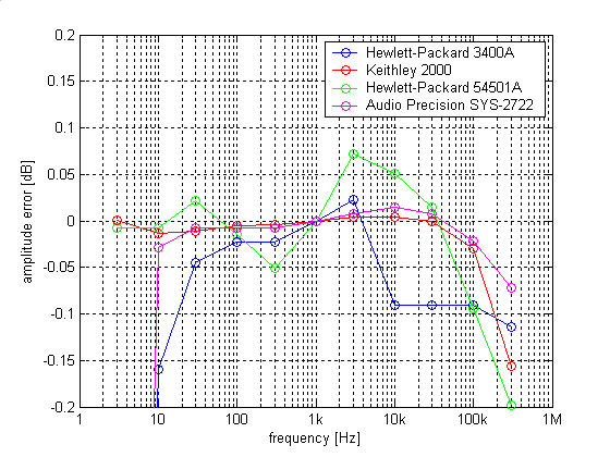
Here some research with respect to meter flatness:

meter_response.png


Source was a HP 3325B. The guaranteed amplitude accuracy of this unit is not particularly narrow, but a self-calibration routine appears to achieve pretty decent flatness. The HP 54501A was used with the built-in RMS function; I hope to improve upon this with importing the waveforms in Matlab and doing the calculation there. The built-in function uses some simplified calculation based on a single signal period--not sure how accurate this is.

Samuel
 
Forgot to mention that the tolerances I gave should apply for the full amplitude range (-80 dBu to +30 dBu), so we need a safety margin for the output amplifiers and attenuators.

Samuel
 
Samuel Groner said:
Forgot to mention that the tolerances I gave should apply for the full amplitude range (-80 dBu to +30 dBu), so we need a safety margin for the output amplifiers and attenuators.

Samuel

I don't follow, are you talking about tolerance for the AGC loop or some external instrumentation?

The loop will presumably be operating at a relatively fixed level, so precision at more than several dB away from that should not be important. Different output levels from the oscillator can be generated with precision gain stages.

Making the AGC accurate over that range, would probably be accomplished by adding a precision gain stage to the AGC loop, but IMO that is adding complexity in the wrong place.

JR
 
* 1 kHz 0.1 dB absolute accuracy
* 3 Hz-30 kHz 0.1 dB relative to 1 kHz
* 3 Hz-300 kHz 0.5 dB relative to 1 kHz

This amplitude accuracy/flatness should apply for the full amplitude range of -80 dBu to +30 dBu. The output stages/attenuators will contribute some error as well (particularly at 300 kHz), so the basic oscillator output (which is of course fixed at +4 dBu) should be reasonably more accurate than the limits.

Samuel
 
OK so thats the target for combined precision of the AGC loop and gain/pad stages. I see no way to practically make this one loop that can compensate for all the error sources.

One exception to making the individual blocks as perfect as possible, is perhaps to tailor the expected errors in the response of the AGC path to mimic the response of the following active stages, so there will be a first order correction. For example- if the AGC loop frequency response rolls off at the same frequency as the active buffer, the osc level will rise as buffer response falls. This requires precision and such poles will hopefully be located well outside range of interest, but coordinating errors that move in opposite directions seems perhaps useful.

JR
 

Latest posts

Back
Top