Mini SSL 5000 Mixer build thread (Revisited 2015)

GroupDIY Audio Forum

Help Support GroupDIY Audio Forum:

This site may earn a commission from merchant affiliate links, including eBay, Amazon, and others.
Hi Mike,

I'm not on the forum all the time, hence the slooooooow response. Also, I'm on a diy sabbatical, hahaha.

First of all, I think it'd be better to continue this conversation in your 7 rail psu thread. This thread is purely meant for Digital Metal's project. I've got the notification option checked for your thread.


Anyway
dual 18v is fine, I built plenty PSU's for 5k cassettes using the JLM PSU with dual 18v trannies.  18v will be somewhere between 20 and 22v unloaded. add the 1.4 rule, that'll be 28 to 30v.

Here a quote from the JLM site, to add explanation :

"What Power Transformer secondary volts do I need?
The transformer secondary AC volts needed depends on the +/- dc regulated voltage rails wanted. If you want +/-34vdc regulated for 99v you will need 37v to 40v unregulated which would need one or two 26vac to 28vac transformer secondary windings. This might sound like a odd voltage value but in reality when you take the fully loaded voltage and add the regulation percentage specified by the transformer manufacture to get the no load voltage it all works out. So if the voltage output of a transformer is stated as 25vac at full load by adding the 10 to 20% regulation amount you will end up with 27.5vac to 30vac unloaded with is perfect. Also if you use one 25vac winding then the refresh rate to the large storage capacitors will be 50 or 60Hz depending on the country you are in. If you use two 25vac windings or a 50vac centre tapped winding the refresh rate will be 100Hz or 120Hz which will almost half the amount of ripple on the large storage caps. Also the dual 25vac has symmetrical ripple. " )


Regarding the 3 rail psu :

Yes, you can apply the negative doubler mod on this one also, but then you'd be using 2 of these for your Xrack/5000 rack after all, right ?

 
helterbelter said:
Hi Mike,

I'm not on the forum all the time, hence the slooooooow response. Also, I'm on a diy sabbatical, hahaha.

First of all, I think it'd be better to continue this conversation in your 7 rail psu thread. This thread is purely meant for Digital Metal's project. I've got the notification option checked for your thread.


Anyway
dual 18v is fine, I built plenty PSU's for 5k cassettes using the JLM PSU with dual 18v trannies.  18v will be somewhere between 20 and 22v unloaded. add the 1.4 rule, that'll be 28 to 30v.

Here a quote from the JLM site, to add explanation :

"What Power Transformer secondary volts do I need?
The transformer secondary AC volts needed depends on the +/- dc regulated voltage rails wanted. If you want +/-34vdc regulated for 99v you will need 37v to 40v unregulated which would need one or two 26vac to 28vac transformer secondary windings. This might sound like a odd voltage value but in reality when you take the fully loaded voltage and add the regulation percentage specified by the transformer manufacture to get the no load voltage it all works out. So if the voltage output of a transformer is stated as 25vac at full load by adding the 10 to 20% regulation amount you will end up with 27.5vac to 30vac unloaded with is perfect. Also if you use one 25vac winding then the refresh rate to the large storage capacitors will be 50 or 60Hz depending on the country you are in. If you use two 25vac windings or a 50vac centre tapped winding the refresh rate will be 100Hz or 120Hz which will almost half the amount of ripple on the large storage caps. Also the dual 25vac has symmetrical ripple. " )


Regarding the 3 rail psu :

Yes, you can apply the negative doubler mod on this one also, but then you'd be using 2 of these for your Xrack/5000 rack after all, right ?

Got it, and you really haven't had any trouble getting the -24 steadily, whereas as far as I've understood, it doesn't need to be regulated.

I still have trouble understanding the unloaded rule of thumb between unloaded or not. I thought the was -24 was indeed drawing wasn't it? So you don't go by the labeled secondary winding to do the 1.4 math but rather by its unloaded state?

I have apparently a supermassive black hole in my pond of electricity knowledge though I try my best to gather all the information necessary and this stuff confuses the shit out of me. Such as a guy once told me I had to do VA (50) divided by the two secondary windings (36), multiplied with 0.6 to get the real DC current drawn until I found it was just a headroom rule if both secondary windings weren't at the same A rate.

DigitalMetal said:
Ok ive just hooked up a SL502 Mono EQ to the bench power supplies and im getting the following readings for current:

+18v = 0.040A
-18V = 0A
-24v = 0.05A

Still no Current draw on the -18v  ??? im going to swap the 2x 18V supplies over in case there is a problem with the power supply giving current readings.

I wanted to hook up a 522 stereo Eq but ive just realised i dont have the drawings/Pinout info for it  :'(

Do you guys have it you could scan/email me? nhester at gmail dot com

I have all the SL521 drawings and some SL502 info i can offer in return attached here:

http://dl.dropbox.com/u/7388077/Racking%20SSL%20SL502%20Mono%20EQ.pdf

http://dl.dropbox.com/u/7388077/SL521%20PinOut%20%26%20Reference.pdf

http://dl.dropbox.com/u/7388077/SL521%20io%20Logic%20%26%20Routing.pdf

http://dl.dropbox.com/u/7388077/SL521%20LineUP.pdf

Could you please reup the schematics again? :prettyplease: :D
 
helterbelter said:
Hi Mike,

I'm not on the forum all the time, hence the slooooooow response. Also, I'm on a diy sabbatical, hahaha.

First of all, I think it'd be better to continue this conversation in your 7 rail psu thread. This thread is purely meant for Digital Metal's project. I've got the notification option checked for your thread.


Anyway
dual 18v is fine, I built plenty PSU's for 5k cassettes using the JLM PSU with dual 18v trannies.  18v will be somewhere between 20 and 22v unloaded. add the 1.4 rule, that'll be 28 to 30v.

Here a quote from the JLM site, to add explanation :

"What Power Transformer secondary volts do I need?
The transformer secondary AC volts needed depends on the +/- dc regulated voltage rails wanted. If you want +/-34vdc regulated for 99v you will need 37v to 40v unregulated which would need one or two 26vac to 28vac transformer secondary windings. This might sound like a odd voltage value but in reality when you take the fully loaded voltage and add the regulation percentage specified by the transformer manufacture to get the no load voltage it all works out. So if the voltage output of a transformer is stated as 25vac at full load by adding the 10 to 20% regulation amount you will end up with 27.5vac to 30vac unloaded with is perfect. Also if you use one 25vac winding then the refresh rate to the large storage capacitors will be 50 or 60Hz depending on the country you are in. If you use two 25vac windings or a 50vac centre tapped winding the refresh rate will be 100Hz or 120Hz which will almost half the amount of ripple on the large storage caps. Also the dual 25vac has symmetrical ripple. " )


Regarding the 3 rail psu :

Yes, you can apply the negative doubler mod on this one also, but then you'd be using 2 of these for your Xrack/5000 rack after all, right ?

Could you also explain what you did with the transformer and the psu and what psu you mostly used? probably jlm?
 
Hi Mike,

I did nothing special with the transformer, I connected it just how the 5 rail psu schematic describes. A 30VA with 2x 18v secondaries is what you need, use 50VA in case you think you need to add something (like an extra micpre).
Connect this to the JLM 5 rail, set up the voltages, add the diodes as I described to the X rack cassette, and you're there. No need to do any mods to the JLM psu, but as said, wire the regulators off-board so you're able to use a larger heatsink.

On a side note, I noticed you mix up VAC and VA. This isn't the same. VAC stands for Voltage AC, VA is Volts Ampere, like Watts.

atticmike said:
I have apparently a supermassive black hole in my pond of electricity knowledge though I try my best to gather all the information necessary and this stuff confuses the sh*t out of me. Such as a guy once told me I had to do VA (50) divided by the two secondary windings (36), multiplied with 0.6 to get the real DC current drawn until I found it was just a headroom rule if both secondary windings weren't at the same A rate.
huh ? I don't get this. Could be, but.... DC current draw ?!? In a transformer ?
Also, the equation looks incomplete to me. How can you calculate the max current from a VA value in case other info is missing (e.g. the used voltage)...... But I can be completely wrong here, the language barrier is troublesome for me as well sometimes, obviously.

I'm not an electronics guru, I can't explain the formulaes that you're showing, I only know that a JLM 5 rail psu with a dual18v secondary transformer does the trick. From experience.

At work I made a simple diagram for you how to connect the diodes between the X rack and the audiovoltage rails. But of course, I forgot to forward them.... Bummer. But I'd be happy to email it to you on monday. If you like.

Don't bother any longer, get yourself the 5 rail PSU from JLM, and a dual 18v secondary transformer, and start building it. Don't torture yourself any longer, hahaha !
;)
 
atticmike said:
...VA (50) divided by the two secondary windings (36), multiplied with 0.6 to get the real DC current drawn until I found it was just a headroom rule if both secondary windings weren't at the same A rate.
This 0.6 factor (or even closer 1/1.8=0.556) has nothing to do with headroom or whatever secondary windings rate but with type of rectification used. Factor 0.6 (or divisor 1.8 ) is used for diode fullwave bridge rectification. Roughly, if your transformer could deliver 1A of whatever AC voltage, the max. DC current of rectified voltage (raw DC voltage=VRMS * SQRT(2)) you could draw with this type of rectification (2 diode drops, doubling mains frequency) would be 0.6A. There are other types (halfwave, voltage doubler, ..) of AC to DC rectification that would use a different factor. Formula isn't complete (IE missing the rectifiers diode drop, ...). Some more in my reply in one of your other threads on the same subject.
 
helterbelter said:
Hi Mike,

I did nothing special with the transformer, I connected it just how the 5 rail psu schematic describes. A 30VA with 2x 18v secondaries is what you need, use 50VA in case you think you need to add something (like an extra micpre).
Connect this to the JLM 5 rail, set up the voltages, add the diodes as I described to the X rack cassette, and you're there. No need to do any mods to the JLM psu, but as said, wire the regulators off-board so you're able to use a larger heatsink.

On a side note, I noticed you mix up VAC and VA. This isn't the same. VAC stands for Voltage AC, VA is Volts Ampere, like Watts.

atticmike said:
I have apparently a supermassive black hole in my pond of electricity knowledge though I try my best to gather all the information necessary and this stuff confuses the sh*t out of me. Such as a guy once told me I had to do VA (50) divided by the two secondary windings (36), multiplied with 0.6 to get the real DC current drawn until I found it was just a headroom rule if both secondary windings weren't at the same A rate.
huh ? I don't get this. Could be, but.... DC current draw ?!? In a transformer ?
Also, the equation looks incomplete to me. How can you calculate the max current from a VA value in case other info is missing (e.g. the used voltage)...... But I can be completely wrong here, the language barrier is troublesome for me as well sometimes, obviously.

I'm not an electronics guru, I can't explain the formulaes that you're showing, I only know that a JLM 5 rail psu with a dual18v secondary transformer does the trick. From experience.

At work I made a simple diagram for you how to connect the diodes between the X rack and the audiovoltage rails. But of course, I forgot to forward them.... Bummer. But I'd be happy to email it to you on monday. If you like.

Don't bother any longer, get yourself the 5 rail PSU from JLM, and a dual 18v secondary transformer, and start building it. Don't torture yourself any longer, hahaha !
;)

I most definitely would want the diagram you made. You could either post it here, on my thread or just mail it to me :)

I know I can be a pain in the ass at times but could you explicitly tell what voltages you ran on the jlm power station?

so you didn't go out before the 317 and ran the -24 over the 317 (having it regulated).

Btw, got the both the 15 and 18v secondary transformers as well as the powerstation for the 5000 modules and ac/dc for the x-rack EQ.
 
Harpo said:
atticmike said:
...VA (50) divided by the two secondary windings (36), multiplied with 0.6 to get the real DC current drawn until I found it was just a headroom rule if both secondary windings weren't at the same A rate.
This 0.6 factor (or even closer 1/1.8=0.556) has nothing to do with headroom or whatever secondary windings rate but with type of rectification used. Factor 0.6 (or divisor 1.8 ) is used for diode fullwave bridge rectification. Roughly, if your transformer could deliver 1A of whatever AC voltage, the max. DC current of rectified voltage (raw DC voltage=VRMS * SQRT(2)) you could draw with this type of rectification (2 diode drops, doubling mains frequency) would be 0.6A. There are other types (halfwave, voltage doubler, ..) of AC to DC rectification that would use a different factor. Formula isn't complete (IE missing the rectifiers diode drop, ...). Some more in my reply in one of your other threads on the same subject.

Ah, okay, now I get it. Thanks for clearing that up, Harpo !


AtticMike,

I'll email you the thingy tomorrow. And yes, I used a 337 rail (not 317) for the -24v rail.
 
helterbelter said:
Harpo said:
atticmike said:
...VA (50) divided by the two secondary windings (36), multiplied with 0.6 to get the real DC current drawn until I found it was just a headroom rule if both secondary windings weren't at the same A rate.
This 0.6 factor (or even closer 1/1.8=0.556) has nothing to do with headroom or whatever secondary windings rate but with type of rectification used. Factor 0.6 (or divisor 1.8 ) is used for diode fullwave bridge rectification. Roughly, if your transformer could deliver 1A of whatever AC voltage, the max. DC current of rectified voltage (raw DC voltage=VRMS * SQRT(2)) you could draw with this type of rectification (2 diode drops, doubling mains frequency) would be 0.6A. There are other types (halfwave, voltage doubler, ..) of AC to DC rectification that would use a different factor. Formula isn't complete (IE missing the rectifiers diode drop, ...). Some more in my reply in one of your other threads on the same subject.

Ah, okay, now I get it. Thanks for clearing that up, Harpo !


AtticMike,

I'll email you the thingy tomorrow. And yes, I used a 337 rail (not 317) for the -24v rail.

thanks, got the mail :)

So basically, the input module has a balanced output right?

Is there a way I could run the compressors output over the input module?
 
Guess I have to go over the inserts "In" in order to place stuff after the HPF / LPF and having it leaving the balanced output of the input module?

Right?
 
DigitalMetal said:
It works !!!

OK i didnt realise that what you show in your diagram, is what i did already have connected, except it was all done via the S502 IDC link,

Ive added this to your drawing here:


Uploaded with ImageShack.us

The reason it wasnt working was that i had linked a wrong pin to -24V via a resistor, as soon as i removed that it all worked  ;D

Now ive just got to copy it 15 more times and get it all in the rack, but the difficult bit is now done!

Thank you so much for your help Paul!

you were saying the stereo input module / mono input still needed the balanced section stuffed?

Because here's a quote from recycledaudio: ". If you are planning to use the SL502 modules without the SL501 or SL505 then the balancing hybrids will need to be added." <-- Talking about either having the input / preamp module in order to have balanced outputs.?

*Edit* Ah, is it by any chance an additional balanced output for monitoring on top of the regular?

*Edit 2* In order to go balanced out with the channel compressor, I do have to go unbalanced out and IN at the insert return on the input module? Whereas I have a general question whether the Input module's both in and output are balanced and therefore the compressors in and output are unbalanced? Could I still make XLR in and key in for the compressor (unbalanced) and after going into the insert return section of the Input module, it'll be balanced? I mean, anything within the circuit is unbalanced anyways and will be balanced at the input module's out, so it wouldn't hurt If used the compressors input as XLR and have it sent to the Input insert return.

On the other hand besides this rather intricate approach of mine, I could also just use the insert send, out the the compressor and the insert return, using the compressors out back into the Input module?

right?

God, I must be giving you such a hard time :D
 
Hi Mike,

No, when using it in a channelstrip you don't need the (de-)balancing parts. It connects straight to the 501/505/521 module via the S502 connection. The button "in"on the 510's frontpanel switches the 510 in circuit.

I sent you the manuals. Read the block diagram of the 521, this shows you in which order the audioparts are :
balanced input > L/R balance > trim > hpf > lpf > Insert > EQ/dyn> output.  The insert can be switched post and pre EQ/Dyn with a switch on the 521, labeled "pre".

The output is unbalanced as this usually feeds the pannermodule. You can use the Direct Out instead, which is balanced, and you have also a dedicated outputgain control. You can select what feeds the DO : Input, prefader, and postfader. Prefader is what you'll use.

So, yes, the 510 comes after the filter section.

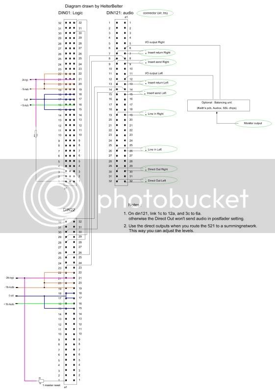
Wire the module as shown here, use only the left audio channels. Check the 510 CCR I sent you for the proper S502 connections, you won't be needing all shown below because you're only using the left channel.

stereochannelstrip521-522V2.jpg

 
helterbelter said:
Hi Mike,

No, when using it in a channelstrip you don't need the (de-)balancing parts. It connects straight to the 501/505/521 module via the S502 connection. The button "in"on the 510's frontpanel switches the 510 in circuit.

I sent you the manuals. Read the block diagram of the 521, this shows you in which order the audioparts are :
balanced input > L/R balance > trim > hpf > lpf > Insert > EQ/dyn> output.  The insert can be switched post and pre EQ/Dyn with a switch on the 521, labeled "pre".

The output is unbalanced as this usually feeds the pannermodule. You can use the Direct Out instead, which is balanced, and you have also a dedicated outputgain control. You can select what feeds the DO : Input, prefader, and postfader. Prefader is what you'll use.

So, yes, the 510 comes after the filter section.

Wire the module as shown here, use only the left audio channels. Check the 510 CCR I sent you for the proper S502 connections, you won't be needing all shown below because you're only using the left channel.

stereochannelstrip521-522V2.jpg

Alright, got that.

Though bear in mind that I'll be using the X-rack EQ and therefore I won't have the "IN" pinout information for the EQ, which means that i'll use a jack input to hook up the input module's out with the x-rack's EQ in?

And in order too hook up the compressor with the input module, I guess i'll just be using the Din22 to 121 EQ information for the compressor? And the key in, can I take those pins and rout them to an xlr output in order to feed it with a signal?
 
Hi Mike,

The X rack eq can be connected to the left channel send and return of the 521 module.

Regarding the connection between the 521 and the 510 : The S502 connection is for Dyn/EQ. So, you can connect a 502/542 eq here, or a 510 compressor, or both.
Once again, the 510 is a straight swap to the 502/542 eq's. The only thing that you might want to add when using a 510, is a connector to the key input (which is balanced by the way).

At work I have a diagram for the mono channel, just like the stereo one that I posted. I can upload this on tuesday.
 
helterbelter said:
Hi Mike,

The X rack eq can be connected to the left channel send and return of the 521 module.

Regarding the connection between the 521 and the 510 : The S502 connection is for Dyn/EQ. So, you can connect a 502/542 eq here, or a 510 compressor, or both.
Once again, the 510 is a straight swap to the 502/542 eq's. The only thing that you might want to add when using a 510, is a connector to the key input (which is balanced by the way).

At work I have a diagram for the mono channel, just like the stereo one that I posted. I can upload this on tuesday.

by connecting to the left channel send and return with the x-rack eq, you talk about sending the dedicated send pin at the Input Module to the input of the x-rack eq (the xlr jack for this instance) and sending the x-rack eq's output back to the dedicated Insert Return at the Input module?

For the compression I got it now by your help since the compression has dedicated send and return pins. And thanks about the key in information which I will hook up with an external XLR input therefore.

Ah a mono diagram for the mono channel compressor to the stereo input module? That'd be great. If you feel like I was depriving you of your information, I could pay you back by an hour rate such as 25 euros for consulting? Regardless of that, once my build is complete by the end of the next week, I'll put up a documentation on this forum in my dedicated thread with similar diagrams / repost yours with reference information about the source.
 
atticmike said:
by connecting to the left channel send and return with the x-rack eq, you talk about sending the dedicated send pin at the Input Module to the input of the x-rack eq (the xlr jack for this instance) and sending the x-rack eq's output back to the dedicated Insert Return at the Input module?
521 Insert send to Xrack input, and Xrack output to 521 insert return, yes.

atticmike said:
For the compression I got it now by your help since the compression has dedicated send and return pins. And thanks about the key in information which I will hook up with an external XLR input therefore.
great. : )

atticmike said:
Ah a mono diagram for the mono channel compressor to the stereo input module? That'd be great. If you feel like I was depriving you of your information, I could pay you back by an hour rate such as 25 euros for consulting?

Haha, no need for that. I have learnt a lot from other people on this forum, this way I can contribute some things as well.

atticmike said:
Regardless of that, once my build is complete by the end of the next week, I'll put up a documentation on this forum in my dedicated thread with similar diagrams / repost yours with reference information about the source.
Great. : )
 
helterbelter said:
atticmike said:
by connecting to the left channel send and return with the x-rack eq, you talk about sending the dedicated send pin at the Input Module to the input of the x-rack eq (the xlr jack for this instance) and sending the x-rack eq's output back to the dedicated Insert Return at the Input module?
521 Insert send to Xrack input, and Xrack output to 521 insert return, yes.

atticmike said:
For the compression I got it now by your help since the compression has dedicated send and return pins. And thanks about the key in information which I will hook up with an external XLR input therefore.
great. : )

atticmike said:
Ah a mono diagram for the mono channel compressor to the stereo input module? That'd be great. If you feel like I was depriving you of your information, I could pay you back by an hour rate such as 25 euros for consulting?

Haha, no need for that. I have learnt a lot from other people on this forum, this way I can contribute some things as well.

atticmike said:
Regardless of that, once my build is complete by the end of the next week, I'll put up a documentation on this forum in my dedicated thread with similar diagrams / repost yours with reference information about the source.
Great. : )

here's a pic of the death row:

eq.jpg


I'll see about my progress by the end of next week and hope it'll turn out as planned.

*Edit* Oh, and also, does the line input feature high-impedance?
 
Thanks a bunch Paul.

That's so awesome :)

That'll help me a lot to turn it into my beloved frankenstein channels trip :D

And line input is for high impedance right?

And direct out is for the knob that's located at the very bottom of the input channel's front plate? (Direct OP, red knob)

Mike
 
Do I also have to strap a resistor to pin 21 or have it passing -24 straight from the psu?

Also, why on one diagram, it says connect pin 28 to -24V with a resistor and on the other, sending it to pin 30 and 32 on the DIN01 logic C side.

Mike
 
atticmike said:
Do I also have to strap a resistor to pin 21 or have it passing -24 straight from the psu?
Pin 21 is connected direct to the -24v line. The resistor must be in front of the masterresetpin 1A.

atticmike said:
Also, why on one diagram, it says connect pin 28 to -24V with a resistor and on the other, sending it to pin 30 and 32 on the DIN01 logic C side.
The other is for wiring the 522/502/510/542 in standalone use. It's a logic line needed to be able to switch in the EQ/dynamics module.
 
helterbelter said:
atticmike said:
Do I also have to strap a resistor to pin 21 or have it passing -24 straight from the psu?
Pin 21 is connected direct to the -24v line. The resistor must be in front of the masterresetpin 1A.

atticmike said:
Also, why on one diagram, it says connect pin 28 to -24V with a resistor and on the other, sending it to pin 30 and 32 on the DIN01 logic C side.
The other is for wiring the 522/502/510/542 in standalone use. It's a logic line needed to be able to switch in the EQ/dynamics module.

Thanks a bunch :)

Got it working. Gonna post pictures and how I proceeded but before I feed the insert with the x-rack eq, isn't the balanced signal of the x-rack gonna cause problems if I feed it to the return of the input module?
 
Back
Top