Mix Bus Compressor from scratch

GroupDIY Audio Forum

Help Support GroupDIY Audio Forum:

This site may earn a commission from merchant affiliate links, including eBay, Amazon, and others.
The question is "where does it stop"
I fully understand that !
I'm just guessing the target of soft compression (3dB) on a master bus will mainly be dictated by MID signal at low freq energy content with the actual SC topology ?
The two common ideas I talk about, which only involves switching passive components, may be easy to test before final decision :)
 
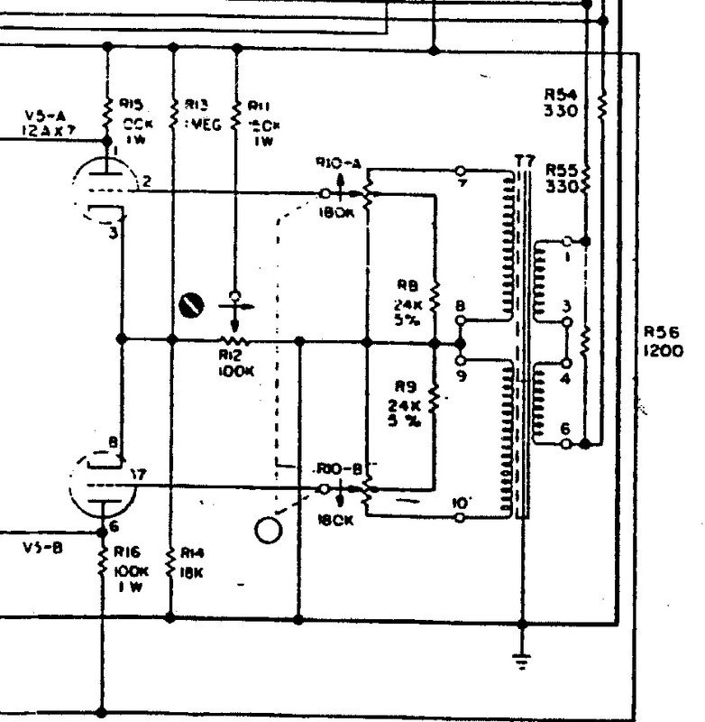
There is a voltage divider from the HT and the threshold control sets the voltage where the tube starts to conduct. If a peak overcomes the threshold, it starts to generate negative DC via the cathode follower. The stage is fed from the output tube which has higher peak to peak voltages than the rms voltages at the output. I hope all that makes sense.
best
DaveP
OK, that makes sense. Is this your own design? I have not seen anything like it before.

Cheers

Ian
 
There was a conversation on this forum between PRR and another member in 2005 about how a Grundig TK19 worked, I took note!
https://groupdiy.com/threads/ef83-6bk8-circuit-examples.9471/#post-112594
It must have worked well because Grundig never changed it over all the models they produced down the years. It must be well out of patent by now...he hopes!
best
DaveP
 
Last edited:
Hi, i am glad for your health!
A compressor with an EF83 tube for gain reduction is a cool project.
It reminds me that the discontinued big Cartec audio THC compressor was around an ef183 for the gain reduction, so not exactly an ef83 but something not too far off.
 
I have not seen anything like it before.
It borrows from a Fairchild 660, there is the voltage divider from the HT and the tubes are biased to cut-off so only the peaks reach the side chain amp.


This is push-pull but its very similar in action
best
DaveP
 
There was a convesation on this forum between PRR and another member in 2005 about how a Grundig TK19 worked, I took note!
https://groupdiy.com/threads/ef83-6bk8-circuit-examples.9471/#post-112594
It must have worked well because Grundig never changed it over all the models they produced down the years. It must be well out of patent by now...he hopes!
best
DaveP
Unfortunately all the links in that thread seem to be dead. I have a copy of H.W. Hellyer's Tape Recorder Servicing book. It has schematics of just about all the Grundig models but not the TK19!!!!! Plenty of later models too but none of them use this circuit.

I notice that PRR said that the control voltage is also fed to the preceding EF86 in the Grundig design so both tube contribute to gain reduction. As the signal is inverted by the EF86 it may also contribute something to thump reduction. When you get it going it will be interesting to see how much gain reduction you actually get and also how little thump you get.

Interesting design.

Cheers

ian
Perhaps this might be of help: https://www.hifiengine.com/manual_library/grundig/tk-19.shtml
 
Thanks for the link. I have been there already but I keep getting an error message that says hifiengine is current unable to handle this request (HTTP ERROR 500).

Cheers

Ian
Yes Ian me too, I ran it up the flagpole in case you had not looked. The link is probably dead or did not upload correctly.
 
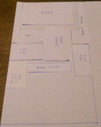
I have finished the design of the chassis and I made scale drawings of the various panels, so I can cut them out with the minimum waste.


The aluminium sheet is 600mm x 1000mm x 1.5mm

There is enough over to allow for any mistakes, I think it will take a while to cut and finish 8 panels to size.
best
DaveP
 
The TK19 does not have that circuit, but just to confuse us, the TK19A does! The A stands for the "automatic" version.
best
DaveP
 
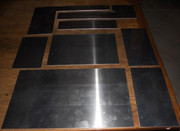
I have made some progress today, all the panels are cut out and finished to size.


To make a tidy box, the dimensions have to be within about a quarter of a millimeter, next job is to join them all together with angle.
best
DaveP
 
We are near the point when DaveP leaves us all shaking our heads as we look at our own mangled attempts at fabricating aluminium chassis...

Hail to the master!
[Hail to the master!] -- (While going through repetitive "bowing-down" gestures and body-movements and chanting): We're not worthy!!! We're not worthy!!! We're not worthy!!! We're not worthy!!!

/
 

Latest posts

Back
Top