MXL microphone circuit simulation, how to simulate the capsule?

GroupDIY Audio Forum

Help Support GroupDIY Audio Forum:

This site may earn a commission from merchant affiliate links, including eBay, Amazon, and others.

MKown

New member
Joined
Feb 20, 2015
Messages
4
Hi guys,

could someone help me with simulation of MXL microphone circuits?
Am using multisim and ltspice and i have some issues with mxl 2001/v67 and mxl 603/990 circuits.
Most of the circuits found on the forum, traced by the members, have capacitor in place of the capsule.
I couldn't find any electrical circuit equivalent for the capsule.
Also, do i proper powered microphone ?
Here's an example of the circuit:
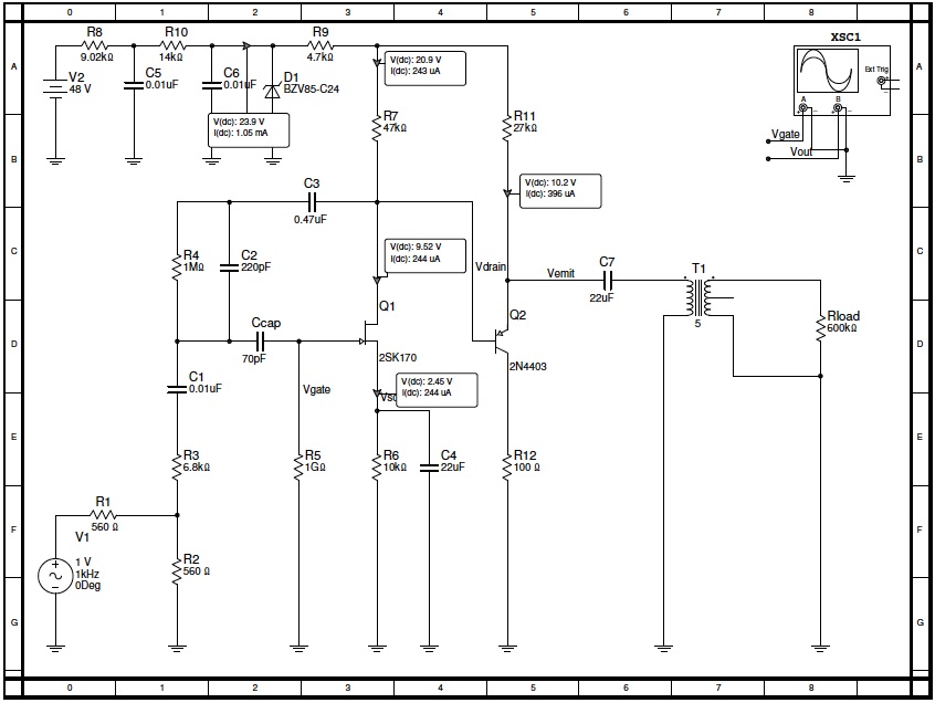
 

Attachments

  • MXL.png
    MXL.png
    31.9 KB · Views: 94
Is there any of the below connections proper? Or should i use only ac source without capacitor?
I want to trace preamp characteristic, to understand which parts and how affect on de-emphasiss eq, but for now i have some issues.
 

Attachments

  • mxl2.png
    mxl2.png
    36.3 KB · Views: 81
Here how I do it:  remember, Neuman gives a hint with their "calibration input" node, which is right where the 560ohm resistor is (which MXL copied):

u87-test1.jpg
 
Thank you very much Matador :-*

Do you have other example for circuits like mxl 603 (schopes type) - without feedback? How inject in those?

How do you modeling transformer in multisum? With standard ms "audio transformer" 4:1 or 10:1 i'm getting weird low/middle cuts at the output... When I used virtual transformer with turn ratio 1 and resistance 160r primary 50r secondary i get the 2:1 finally, but i'm not sure is't proper working...

The last question is about mxl 2001 circuit :) If i would like to use one resistor to bias the fet and  put 1G (R5 on your schematic) resistor to ground like in u87, how should I connect potentiometer to verify proper resistance? 1 and 2 leg of potentiometer to the source and 3 to ground?

Thanks again!
 
RuudNL said:
Are you sure the 10 nF (left-top) is correct?
As far as I remember Neumann used 33 or even 47 nF.

Hello  RuudNL,

10nF is probably residue from chinese microphone versions :)
As you visited this thread, could you look on my newbie questions from the previous post.
I've read many of your posts, so i assume this would be some obvious things with your knowlege :)
 
About the test configuration: I agree with Matador, you should inject the test signal at the node R2/R3.
This is the way Neumann advises how to measure the frequency response of the electronics in the U87 microphone.
 
MKown said:
How do you modeling transformer in multisum? With standard ms "audio transformer" 4:1 or 10:1 i'm getting weird low/middle cuts at the output... When I used virtual transformer with turn ratio 1 and resistance 160r primary 50r secondary i get the 2:1 finally, but i'm not sure is't proper working...

I don't quite remember:  but you need to specify primary H at least so the sim knows what the bass response will look like.  LTSpice lets you specify both resistance and inductance (and parallel capacitance for that matter).

MKown said:
The last question is about mxl 2001 circuit :) If i would like to use one resistor to bias the fet and  put 1G (R5 on your schematic) resistor to ground like in u87, how should I connect potentiometer to verify proper resistance? 1 and 2 leg of potentiometer to the source and 3 to ground?

Thanks again!

You mean substitute R6 in my schematic with a pot?  Yes, 1-2 to source, and 3 to ground.
 

Latest posts

Back
Top