Neumann M49 Clone : Build Thread Puck Style (TLM49 Conversion To M49 b-c)

GroupDIY Audio Forum

Help Support GroupDIY Audio Forum:

This site may earn a commission from merchant affiliate links, including eBay, Amazon, and others.
"Input1: Series – BLUE and BROWN, Jumper GRAY to VIOLET
Parallel – BLUE and BROWN, Jumper BLUE to VIOLET, GRAY to BROWN

Output1: Series – BLACK and YELLOW, Jumper RED to ORANGE
Parallel – BLACK and YELLOW, Jumper BLACK to ORANGE, RED to YELLOW"

So on the AC input, Blue and Violet together, and Gray and Brown together. 

On the output, Black and Orange together, and Red and Yellow together.

My question is, if I maintain the proper parallel wiring as in wire Blue and Violet to neutral, and Gray and Brown to Hot on my IEC, does this dictate which pair of secondaries goes to either spot on the PSU board?  Or is phase reversal at the PSU not possible?  I don't see reference to such a distinction on the PSU schematic pg1 one of this thread. 

Another way of saying it - does Blue and Violet on the primary side = Black and Orange on the secondary side?  Or does it = Red/Yellow, or neither?  I feel like there is a piece of basic information I don't understand here.  Since the voltage is only transferred via magnetism, does this direct relationship not exist?
 
The data sheet makes sense.  This reads like paralleled windings on the primary.  As for the secondary, the voltage is rectified so the polarity of the AC on the rectifier input makes no difference as long as the rectifier itself is installed properly.  Some of those rectifier bridge assemblies have the AC inputs, and the + and - DC outputs marked or embossed on the case.
 
Thank you for clearing that up.  I can understand this transformer now.

I see on the PCB where I am to connect AC20v as well as AC120v, and they both go to a series of diodes on the PCB.

So the next thing is looking at the 20v transformer, I assume this is stepping down from 115v to 20v.  Shown here as 187b20 http://www.mouser.com/ds/2/177/186-187-948805.pdf

Looking at the lugs here https://www.hammfg.com/files/products/186-187/186-187bulletin.pdf in figure 7b, I see lugs 2/3 are the primary with lug 2 being the coil start of the primary.

On the secondary side, I see 5-7(7 is a center tap) is one coil, and 5-8 is both coils, with 5 being coil start.  I am not clear on which two lugs to wire on the secondary to get 20v here.  I've read both sheets and I can't seem to find a description like the toroid has.  I assume this is because I don't have the basic knowledge of reading a transformer schematic correctly.  Could you give me a hint on how I know which lugs to use on the secondary of the Hammond?

There is also the small issue of this Triad filter reactor as well.  I apologize for being uneducated here.  I am looking at the PSU schematic from page one and I don't see what is what here.
 
After one week my M49 work flawless it stopped passed audio today :(
I was really shocked and went to trouble check.
I noticed, that H+ is still on 6,2v and K is 1,6V.
But now it comes.
B+ is hanging on 0,9v to 1,1v instead of 120v.
I biased my B+ trimmer to 119,8v.
What is happened ?
The Tube still burns and no capacitor in the PSU seams to be broken. No smoke and so one.
What could happened ?
Where I've to start my trouble check ?
Hope you guys can help me.

EDIT: Found the mistake. I burned my fuse. I just had to find out, why my fuse burned down
 
Need to figure out why the fuse blew... Unless there is a short or other problem, the fuse should not fail...
 
i have a b version and i am confused on how to measure the 1.6v bias. i have 120 at pad5,  50v at r10.  h+=6.1v  k=6.1 v. is ther a place i can mesure the 1.6v in the b version?
 
To bias 1.6V from grid to cathode measure across R6.

Is your R10 100k (like the schematic)?

Bias based on current to start. Here's how I'm re-biasing with my newly installed 6S6B:

-record a test clip
-clip one DVM lead to R7 on the power supply
-unscrew the mesh from the mic body
-mute input on DAW
-measure voltage at tube plate (was 64V after tube swap for me)
-adjust bias pot to see 73V (73 across 100k is 0.73mA)
-slide mesh back on without installing screws
-record test clip @ 0.73mA
-repeat steps above for 0.67mA, 0.68mA, 0.69mA, etc
-go to sleep and compare clips the next day

There will be some drop from the power supply to R10 but since I'm biasing by ear anyway it doesn't matter. At 0.7mA that drop is probably negligible anyway.
 
yes i have 100k plate resistor. here are my voltages  6s6b tube  cinemag cm6511
b+ 120.5
r10 50v  120-50= .7 should be good i think
h+6.1v
bias 1.07v  this seems pretty  low  from the 1.6  this was measured at across r6. should i try to get this higher with a trimmer across r10 to get that closer? 
back plate polarization voltage between node r8 and r9    57.2v
I think from what i have read i may be close but wasn't sure if i need to try to tweak bias closer to 1.6v
 
R10 is your load. No need to adjust. Adjust your bias with a trim pot in R7. If you used Dany’s BOM you should have one there.

Don’t worry about the 1.6V or 0.73mA. Pick one for a starting point and adjust your bias by ear. If you have the equipment to inject a tone and measure THD you can bias faster and more accurately than by ear. I don’t so I do it by ear. I use my own voice even though I’m a terrible singer. I find it helps because I know it well.

Both 1.6V and 0.73mA are based on the AC701. To get the most out of your 6S6B you may have to change your bias, C4 and R10. Start with the bias, then C4 then R10. You may have to re-bias when changing components.
 
the mic sounds good it does have lower out put then the u47. But sounds good. I also have a small hum but may need to burn in the tube.  not sure if that is where its coming from but i will burn it in for awhile and see if that helps. I will tweak r7 more  and try some of your suggestions and and record some clips with different bias settings and see where that takes me. 
 
When adjusting your bias give it a moment to settle before measuring or remeasure before each re-adjustment. The bias may be easier (and safer) to adjust with a trim pot adjuster rather than a screw driver. If you don't have one, order it when you put together your next project cart. They're useful to have.

https://ca.mouser.com/ProductDetail/Bourns/H-90?qs=sGAEpiMZZMtC25l1F4XBU6Oesurqb%2f2Mwxsc%2f5lXeb4%3d

Also, remember that the anode has enough potential to pop a fuse so be very careful poking leads in there while the mic is still in its body.

Shut down your power supply while listening to the mic and see if your hum immediately goes away with the power off. The tube is still hot and the caps have your 116V still up. If the hum immediately goes away it's probably your power supply.

I had trouble on this mic with hum. Lots of trouble. I used the same grounding scheme as my 251 and U67. I had even thought it was poor choke orientation since I crammed it into a small chassis. I bought a new Dandeurloo case, rebuilt it and had the same issue. I had tried other grounding  schemes (lifting shield from 0V in mic) with no success.

Finally I reterminated the shield to 0V inside the mic, ran the pin 3 (shield) to the PS PCB through a switch and lifted the 0V connection to ground inside the PCB - all based on mrerdat's scheme (like the Neumann schematics).

https://groupdiy.com/index.php?topic=50021.msg796487#msg796487

It fixed it. The PS chassis is grounded at the IEC plug. When the switch is open the PCB in the PS only receives ground reference via the mic (inside the mic 0V is tied to the shield).

I'm still not sure why only this mic had the problem but I'll be modifying my other power supplies to match.
 
Also, M49 levels vs U47 levels. Are you comparing with your U47 in omni? U47 in cardioid will be 4dB or so louder because the back diaphragm is disconnected (no longer in parallel with the front). You can do the same on an M49 if you install a switch or relay.
 
good info thanks  i'll check all this and see what i end up with. thanks for all your help! Scot
 
Hi all,
I would really appreciate your help with a strange problem with my m49b style mic.

So I read both threads and didn't find anything pointing me in the right direction...

When trying to bias the tube I tried to get around 60V at the anode and around 1.6 at  R6, the problem is that when I'm around those voltages the tube sounds as if it is switching on an off.
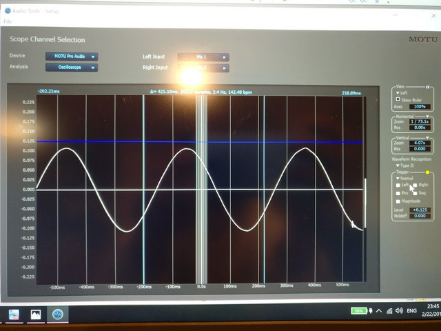
When I connected the mic to an oscilloscope it shows a sine wave when there is no signal at all.
Very strange.
When I turn R7 at both ends the sine wave disappeared slowly, but I'm getting 120V at anode and 4.7v at R6

What am I doing wrong? :eek:

Thanks
Moshe
 
Unless you're using an AC701 don't expect to meet both the bias voltage and current specified on the schematic. I used the idle current to bias because it's the easiest to track (73V across 100k = 0.73mA). My 6S6B is biased for 0.69mA (for now).

Your bias is roughly 0.60mA if your supply is 120V which is close enough to pass audio properly.

A sine wave with no input? I would guess 100Hz from your power supply. Can you check what the frequency is?

If your mic sounds as if it is switching on and off, I would suspect something is wrong with your wiring - possibly in the bias. If this is the case, it would be best to carefully look everything over without powering up your mic. Unless you mean the mic sounds as if it's switching on and off while you're measuring voltage. Don't measure at the tube grid like the schematic shows! Measure across R6.

As always with mics, make sure everything is clean - especially in the Hi-Z components!

https://groupdiy.com/index.php?topic=58771.0
 
Delta Sigma said:
Unless you're using an AC701 don't expect to meet both the bias voltage and current specified on the schematic. I used the idle current to bias because it's the easiest to track (73V across 100k = 0.73mA). My 6S6B is biased for 0.69mA (for now).

Your bias is roughly 0.60mA if your supply is 120V which is close enough to pass audio properly.

A sine wave with no input? I would guess 100Hz from your power supply. Can you check what the frequency is?

If your mic sounds as if it is switching on and off, I would suspect something is wrong with your wiring - possibly in the bias. If this is the case, it would be best to carefully look everything over without powering up your mic. Unless you mean the mic sounds as if it's switching on and off while you're measuring voltage. Don't measure at the tube grid like the schematic shows! Measure across R6.

As always with mics, make sure everything is clean - especially in the Hi-Z components!

https://groupdiy.com/index.php?topic=58771.0

Hey thanks a lot for taking the time to answer!

The mic does switch on and off not while measuring voltage but during the bias process. I tried to bias by ear and then measure voltage.

Maybe my biasing process is not right?
My steps are as follows,
1. Set the heater Voltage to 6.2V with a 47ohm resistor.
2. Set the b+ voltage to ~120V.
3. Connect the mic and let the tube heat up for 20 minutes
4. Measure across R6.
5. Listen and adjust R7.

When I reach a normal biasing voltage the mic become unusable.

When you say "wrong with the wiring" in the bias what do you mean?

On a side note, I tried already two different tubes, one 5840w and one 6s6b.
Both have exactly the same symptoms.

Thanks again
Moshe
 
Check for shorts. Make sure the high impedance section is clean. I meant capsule bias, I should've been clear. If something is dirty or shorted anywhere that 120V supply goes, it could cause intermittent on/off sound.

I don't have anywhere near the experience as others here though. Maybe if you recorded a sample and posted here someone else would know where to look.

Check for shorts in in your cable too.
 
Delta Sigma said:
Check for shorts. Make sure the high impedance section is clean. I meant capsule bias, I should've been clear. If something is dirty or shorted anywhere that 120V supply goes, it could cause intermittent on/off sound.

I don't have anywhere near the experience as others here though. Maybe if you recorded a sample and posted here someone else would know where to look.

Check for shorts in in your cable too.

n5XcWaAvJaYvOSyQqY_N9t1wW1E8TPb82nYsWe9NIMNtAvQmZ9AJLUdj8xAZxxeSPHjGivofy520J6i9syLUbC68jGNCl-8mO7pefnnX3Udj0ZbslIxITbZac-zQZ0nJrdxTP7yKDZF4cirUAB_AGgGfuLHgWBUOLUq3hX8JSuZ7rDt_G-tt3LWHGUsaSeoUN2b0nHogeCo6oJeIZodzyjshfftOz0RLsxWpvr0vODKFaS2Q_65NlKJsYObV9YPABT09vJKrroWTdVy3AbHpVkdB9GV_I9u4_CvcrDSUOpikPQf0XIeq1jVmoGZjMkg1wWWy45-mWqmASN0HIongRsoLhydAr3NAed_QA4KRSjQcFItyTr-XzU-OgHvLAePiV3TuuRFAu-78GzGGHXqMoPz_r6_iXwJ49WxFGYZjyY56DPgTUSs4XLOaDBKuGe8DKO8Qe73bTJ97BC-a_Y95wB2UCH8Cax46NEi4cSbReXg6gEIjjgVpLTfuy-Xf-l2lZ9PsRi4nEgW9wFdZRkeHOUuYF5tMX80qjkCWK_WuAeOv3bA8203DtqQvKkb-iCR1sggvxtdsKI9okuZUi6Q5nVoG5IJEl9j_tupn2_IW=w1040-h780-no


Here is a picture of the noise I get. It's 2.4Hz.

The noise only goes away when I turn R7 in the mic fully anti clockwise. (which means full 2Mohm resistance?)
In this situation voltages are:
B+ =124V
H+ =6.1V
Across R10 = 6V
plate =117V
across R6 = 5.99

I also cleande the capsule bias section again using IPA 99%.
It didn't solve the problem.

Cheers
Moshe
 
The picture didn't load for me. 2.4Hz is odd; can't say I have any ideas on where to go but I would avoid biasing so far off and troubleshoot with the bias set close to where it should be.
 
Delta Sigma said:
The picture didn't load for me. 2.4Hz is odd; can't say I have any ideas on where to go but I would avoid biasing so far off and troubleshoot with the bias set close to where it should be.

I'll try the picture again.


I think I'll heed your advice, I now just let the mic run for a day or so to see if maybe it has something to do with the tube.


Latest posts

Back
Top