Neumann U67 Clone : D-U67 Tube Microphone Build Thread.

GroupDIY Audio Forum

Help Support GroupDIY Audio Forum:

This site may earn a commission from merchant affiliate links, including eBay, Amazon, and others.
micaddict said:
Now that this is settled, it would be nice to have some new A/Bs between the AMI and ioaudio tranny in the D67. For sound that is.
Any chance this could happen? E.g. two members getting together somehow. Both mics should have the "same" capsule at least.
Or Dany, will you be building two anywhere in the near future?

Hi.
I'll try to run some test Thursday/Friday.
 
I'm gonna do this mod today, I have original modern k67
Neumann Capsule and have original vintage u67 here I can do test up against. I'm in la if someone wants to join in on the test
 
Studio Mollan said:
micaddict said:
Now that this is settled, it would be nice to have some new A/Bs between the AMI and ioaudio tranny in the D67. For sound that is.
Any chance this could happen? E.g. two members getting together somehow. Both mics should have the "same" capsule at least.
Or Dany, will you be building two anywhere in the near future?

Hi.
I'll try to run some test Thursday/Friday.

:)
 
Ok, ive run a new test. IOaudio version as they are and AMI T67 version converted as instructed by Dan.

Converted AMI
https://dl.dropboxusercontent.com/u/42125780/U67%20T67%20Take%201%20Reversed%20as%20instructed.wav

IOaudio
https://dl.dropboxusercontent.com/u/42125780/U67%20IOaudio%20Take%201%20reference.wav

Please listen and share your thoughts. 
/
Emil


EDIT:
When only reversing 5-12 the pad starts to behave strange. With pad engaged it seems to roll of a lot of high end, and actually makes it sound a lot like the IOaudio transformer. Am i on to something here? Take a lsiten below.

AMI T67 only reversed 5-12 with -10db pad in.
https://dl.dropboxusercontent.com/u/42125780/U67%20T67%20reversed%205-12%20only%20with%20pad%20take%203.wav

IOaudio
https://dl.dropboxusercontent.com/u/42125780/U67%20IOaudio%20reference%20take%203.wav


When only reversing 5-12 the pad starts to behave strange. With pad engaged it seems to roll of a lot of high end, and actually makes it sound a lot like the IOaudio transformer. Am i on to something here? Take a lsiten below.

The answer is yes cause the pad is tied to the feedbackloop in the filter network below it , Since only swapping 5-12 create phase inversion and phase shift it will affect the whole feedback function,  if you swap the 3 pair as previously suggested your correct all the phase and feedback issue so the pad should not affect the response
except for the output.

I would defo suggest that you experiment with the feedback cap value for the IOaudio transformer to see if a lowest or highest possible value to see how it impact it,

hope this helps,
Best,
Dan,


poctop said:
When only reversing 5-12 the pad starts to behave strange. With pad engaged it seems to roll of a lot of high end, and actually makes it sound a lot like the IOaudio transformer. Am i on to something here? Take a lsiten below.

The answer is yes cause the pad is tied to the feedbackloop in the filter network below it , Since only swapping 5-12 create phase inversion and phase shift it will affect the whole feedback function,  if you swap the 3 pair as previously suggested your correct all the phase and feedback issue so the pad should not affect the response
except for the output.

I would defo suggest that you experiment with the feedback cap value for the IOaudio transformer to see if a lowest or highest possible value to see how it impact it,

hope this helps,
Best,
Dan,

Thanks fr clarifying that Dan!
I'll try out some other values for C17 on the IOaudio builds. After listening to the now correct AMI T67 I'm still not convinced that my IOaudio versions are correctly wired. I going to have to go through my wiring again.
I find my last comparison in the above post a bit intriguing. When I only reverse 5-12 on the AMI with -10dB pad engaged it sounds pretty much exactly as the IOaudio. Is it possible I could have reversed or misplaced some components/switches etc? The air is simply not there in my IOaudios. The difference in sound between the two is still I think to large just to be caused by different brands of transformers.
Any help here would be very appreciated. Any way to measure polarity in the IOaudio transformer? Maybe accidental polarity change?
/
Emil
 
One way is to disconnect the trafo and tone out all the pins/coils while also notating DCR values.
Make a sketch of all the coils and the termination ends/pin-numbers.
You'll need a scope and a tone generator so you can determine polarity from I to O (or pri-to-sec).... Notate which pins are + and which are - with respect to the source signal and associated pins.

Once you know and have notated which coils are which and which pins are +/- for each coil then review the documentation for that trafo as well as the wiring/linking diagrams, u67 schematic, and tone out the PCB traces to confirm that all the +'s and -'s are connected as specified in the schematic.

If you'e got a tone gen and scope hooked up you may also want to compare saturation levels and phase response WRT frequency between similar style transformers or various suppliers transformers.

You can also measure the AC Signal voltage (from the tone gen) at pri/sec to determine/confirm the ratio.

Once that's all good to go it should be connected up in-circuit (terminated to a pre) while using the CAL input to send signal in, sweep, and scope at the various ckt-nodes to confirm multiples of the same build are "within spec" of each-other.

Cheers,
jb
 
0dbfs said:
One way is to disconnect the trafo and tone out all the pins/coils while also notating DCR values.
Make a sketch of all the coils and the termination ends/pin-numbers.
You'll need a scope and a tone generator so you can determine polarity from I to O (or pri-to-sec).... Notate which pins are + and which are - with respect to the source signal and associated pins.

Once you know and have notated which coils are which and which pins are +/- for each coil then review the documentation for that trafo as well as the wiring/linking diagrams, u67 schematic, and tone out the PCB traces to confirm that all the +'s and -'s are connected as specified in the schematic.

If you'e got a tone gen and scope hooked up you may also want to compare saturation levels and phase response WRT frequency between similar style transformers or various suppliers transformers.

You can also measure the AC Signal voltage (from the tone gen) at pri/sec to determine/confirm the ratio.

Once that's all good to go it should be connected up in-circuit (terminated to a pre) while using the CAL input to send signal in, sweep, and scope at the various ckt-nodes to confirm multiples of the same build are "within spec" of each-other.

Cheers,
jb
Wow thanks! Ill try to get my scope running and try that out. Think ill start of by going through my wiring one more time.
/
Emil
 
Studio Mollan said:
poctop said:
When only reversing 5-12 the pad starts to behave strange. With pad engaged it seems to roll of a lot of high end, and actually makes it sound a lot like the IOaudio transformer. Am i on to something here? Take a lsiten below.

The answer is yes cause the pad is tied to the feedbackloop in the filter network below it , Since only swapping 5-12 create phase inversion and phase shift it will affect the whole feedback function,  if you swap the 3 pair as previously suggested your correct all the phase and feedback issue so the pad should not affect the response
except for the output.

I would defo suggest that you experiment with the feedback cap value for the IOaudio transformer to see if a lowest or highest possible value to see how it impact it,

hope this helps,
Best,
Dan,

Thanks fr clarifying that Dan!
I'll try out some other values for C17 on the IOaudio builds. After listening to the now correct AMI T67 I'm still not convinced that my IOaudio versions are correctly wired. I going to have to go through my wiring again.
I find my last comparison in the above post a bit intriguing. When I only reverse 5-12 on the AMI with -10dB pad engaged it sounds pretty much exactly as the IOaudio. Is it possible I could have reversed or misplaced some components/switches etc? The air is simply not there in my IOaudios. The difference in sound between the two is still I think to large just to be caused by different brands of transformers.
Any help here would be very appreciated. Any way to measure polarity in the IOaudio transformer? Maybe accidental polarity change?
/
Emil

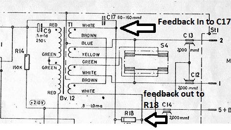
Hi Emil,  I went in and rechecked again... and triple checked again all connection on the Mic PCB for Max Transformer and everyting is Inine with Max documentation I have identified on this picture what could be the ony thing that might be a little confusing but in all in makes senses and i iam 100% everything is correct with IOaudio transformer ( Polarity of feedback and Phase )unless there is an error on Max traffo document wich i doubt very very much , you coud still consut him if you have any questions on his transfo

I am gad you made those point as i am always willing to re-re validate my work, cause no ones is perfect,
those are the connection point i used in regards to Max Specifications, even if I had made a mistake wich is not the case here the mic should sound brighter wich would point to having the feedback not functionning or inverted wich is not the case here wich is seems to sound darker, i am starting to think you might actualy switch the capsule as no assumption can be made for a critical part ike this ,

Hoping I can hep on this matter,
Best,
DAN,


nomenclature from Max Spec sheets,
58d028199417b.jpg

 
It may not be a problem the feedback with Max's transformer... the size of C9 has an effect on the sound of a microphone as it interacts with the inductance of the transformer primary.  But this (in my testing experience) is most apparent in the transformer low end.

if you swap the 3 pair as previously suggested your correct
I don't understand how swapping all three windings makes any change at all to the circuit! This is basic transformer 101, right? The ends of the windings don't have any absolute polarity.
I'm really scratching my head as to how this is making a difference. 
 
dmp said:
It may not be a problem the feedback with Max's transformer... the size of C9 has an effect on the sound of a microphone as it interacts with the inductance of the transformer primary.  But this (in my testing experience) is most apparent in the transformer low end.

if you swap the 3 pair as previously suggested your correct
I don't understand how swapping all three windings makes any change at all to the circuit! This is basic transformer 101, right? The ends of the windings don't have any absolute polarity.
I'm really scratching my head as to how this is making a difference.

+1 this is exately what i wanted to post as well 2 seconds late,  since the same core pcb as been used for the T67 and the MAX BV12,
i would like to remind that the swap fix only applies to AMI T67 not to confuse furthermore , i have toroughy check Max config on the pcb and everything is correct ,  when i made the mistake initialy with AMI T67 i have on purpose made all the connection mirrored but as you pointed out the feedback winding is assymetric then the relation with the primary needs to folow that is why , you can hear the difference from the sample Dan have made in the previous page and it is day and night it sounds so much sweeter on the top end with the correction. as far as of now i am thinking that C17 woud need to be experimented with for Max transformer,  as pointed out earlier the amplifier test with max traffo is in specification hence it seems to point out on the capsule,

hope this helps,
Best,
dan,
 
poctop said:
dmp said:
It may not be a problem the feedback with Max's transformer... the size of C9 has an effect on the sound of a microphone as it interacts with the inductance of the transformer primary.  But this (in my testing experience) is most apparent in the transformer low end.

if you swap the 3 pair as previously suggested your correct
I don't understand how swapping all three windings makes any change at all to the circuit! This is basic transformer 101, right? The ends of the windings don't have any absolute polarity.
I'm really scratching my head as to how this is making a difference.

+1 this is exately what i wanted to post as well 2 seconds late,  since the same core pcb as been used for the T67 and the MAX BV12,
i would like to remind that the swap fix only applies to AMI T67 not to confuse furthermore , i have toroughy check Max config on the pcb and everything is correct ,  when i made the mistake initialy with AMI T67 i have on purpose made all the connection mirrored but as you pointed out the feedback winding is assymetric then the relation with the primary needs to folow that is why , you can hear the difference from the sample Dan have made in the previous page and it is day and night it sounds so much sweeter on the top end with the correction. as far as of now i am thinking that C17 woud need to be experimented with for Max transformer,  as pointed out earlier the amplifier test with max traffo is in specification hence it seems to point out on the capsule,

hope this helps,
Best,
dan,

Thanks for all this valuable info guys!!
I'll run some more tests as soon as I can. A fellow forum member who's also helping out.
I'll switch capsules between the two versions to rule out capsule issues.
Then maybe removing c17 on both to see how the two different transformers behave without the feedback circuit. That might shed some light on the issue.
/
Emil

++++++++1

dD
 
I've been experimenting with C17.  I apologise for the omission of frequency sweeps and the general lack of a scientific approach in the following.  These were kind of quick and dirty tests to see what difference (if any) swapping out values for C17 would make to the top end in this mic. 

I went above and below the range of values suggested in the schematic at Dany's suggestion.

The mics in the sound samples are two DU67s with Max's BV12s, Beesneez K6s and NOS Silver Shield Telefunken EF86s.  I left one stock (100pf) and changed values of C17 in the other.

Here are some sound samples with speech, singing and tambourine.  The mics were side by side for the bulk of the recordings. 

180pf v Stock

Stock Speech then Singing
180pf Speech then Singing
Stock Tambourine
180pf Tambourine

68pf v Stock

Stock Speech
68pf Speech
Stock singing
68pf Singing
Stock Tambourine
68pf Tambourine


For these last two I sang directly into each mic.  Different takes obviously.


Stock singing direct
68pf Singing direct

Any feedback (Hur Hur  :p) very welcome.  Please forgive the inconsistencies of my warble and the varying timbres and keys  :eek:

Peace

Jim
 
Jim50hertz said:
I've been experimenting with C17.  I apologise for the omission of frequency sweeps and the general lack of a scientific approach in the following.  These were kind of quick and dirty tests to see what difference (if any) swapping out values for C17 would make to the top end in this mic. 

I went above and below the range of values suggested in the schematic at Dany's suggestion.

The mics in the sound samples are two DU67s with Max's BV12s, Beesneez K6s and NOS Silver Shield Telefunken EF86s.  I left one stock (100pf) and changed values of C17 in the other.

Here are some sound samples with speech, singing and tambourine.  The mics were side by side for the bulk of the recordings. 

180pf v Stock

Stock Speech then Singing
180pf Speech then Singing
Stock Tambourine
180pf Tambourine

68pf v Stock

Stock Speech
68pf Speech
Stock singing
68pf Singing
Stock Tambourine
68pf Tambourine


For these last two I sang directly into each mic.  Different takes obviously.


Stock singing direct
68pf Singing direct

Any feedback (Hur Hur  :p) very welcome.  Please forgive the inconsistencies of my warble and the varying timbres and keys  :eek:

Peace

Jim

Great! I can't seem to get to the files though.
/
Emil
 
Jim50hertz said:
Links fixed  8)

There's difference, really subtle. I dont think swaping C17 will solve this dullness that we are experiencing.
Great test Jim!


I looked at the schematic and found another filter. C12+C13. A long shot maybe but if the transformers have different DCR on the secondary could that affect the cut of of that filter? I dont know how to calculate the cutof. This is a radio interference filter? 
/
Emil

 
I have do the complete mod. (5-12,1-4,7-10) and no sound change...I have compared with another no mod. Tomorrow I will try only 5-12
 
kaguenpituak said:
I have do the complete mod. (5-12,1-4,7-10) and no sound change...I have compared with another no mod. Tomorrow I will try only 5-12

Now thats weird, this would suggest that the feedback circuit IS symmetrical!!... We shouldn't have to be here testing and guessing polarities and windings of Oliver's transformers. I think he needs to explain exactly the windings on his T67.
 
Back
Top