Neumann U67 Clone : D-U67 Tube Microphone Build Thread.

GroupDIY Audio Forum

Help Support GroupDIY Audio Forum:

This site may earn a commission from merchant affiliate links, including eBay, Amazon, and others.
poctop said:
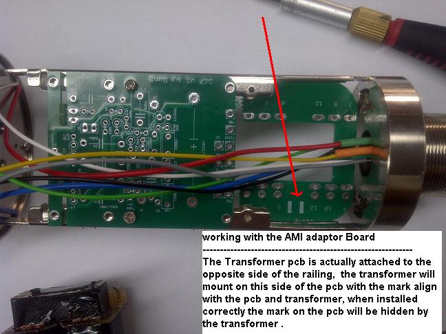
Congrats to Wave for is really nice build 8) , Dave was involved at the very first stage of the developpment of the D-U67 microphone as you can see that he has etched his own adaptor board,  I was allowed to post picture of his new toy,  Keep us posted,  I do like the AMI transformer look  8)

AMIA.JPG

AMIB.JPG

Best,
Dan,
This is a photo of my etched pcb. It looks to me that mine is installed in what would be from the backside and 180 degrees rotated than Dany's production PCB...basically the black lines on the transformer are underneath the etched line markings not facing...
or maybe I'm crazy

Dave
 
dmp said:
Even if the transformer was mirrored, it is symmetrical. It shouldn't make a difference.

Im not sure if this is entirely the case though. it all depends on what the windings are doing inside the transformer.

I have a spare t67 here unmounted. tell me the test to do and ill do it.
 
wave said:
poctop said:
Congrats to Wave for is really nice build 8) , Dave was involved at the very first stage of the developpment of the D-U67 microphone as you can see that he has etched his own adaptor board,  I was allowed to post picture of his new toy,  Keep us posted,  I do like the AMI transformer look  8)

AMIA.JPG

AMIB.JPG

Best,
Dan,
This is a photo of my etched pcb. It looks to me that mine is installed in what would be from the backside and 180 degrees rotated than Dany's production PCB...basically the black lines on the transformer are underneath the etched line markings not facing...
or maybe I'm crazy

Dave

cheers dave,

ok this is interesting.

my black markings on the transformer are under the numbers side of Dany's mount. (The same orientation as yours / top side in your lower picture). Therefore you have bridged the opposite sides of the transformer than I have.

Can you list where the cable colors end up on your main pcb please?

cheers, jesse
 
I would hook a 1 kHz sine wave up to the primary and then compare each of the other windings to it by looking at them on the scope. On the scope you can see if they are in phase or out of phase with respect to the primary and what the voltage levels are.
You should be able to hook it up and measure the correct voltage ratios  - primary to secondary should be 7:1 and the primary to feedback should be 22:1.

If you try this and things seemed really baked, i.e. you aren't seen clean sine waves on the seconday & feedback, then look into whether the two individual windings of the primary / secondary / feedback are out of phase with each other.
 
wave said:
poctop said:
Congrats to Wave for is really nice build 8) , Dave was involved at the very first stage of the developpment of the D-U67 microphone as you can see that he has etched his own adaptor board,  I was allowed to post picture of his new toy,  Keep us posted,  I do like the AMI transformer look  8)

AMIA.JPG

58d02819941bb.jpg

Best,
Dan,
This is a photo of my etched pcb. It looks to me that mine is installed in what would be from the backside and 180 degrees rotated than Dany's production PCB...basically the black lines on the transformer are underneath the etched line markings not facing...
or maybe I'm crazy

Dave

Thanks Dave yes your are not crazy,  as i did a good job (mistake) mirroring it , you install the transformer adaptor backwards or should i say the right way now, ;)
it is so fortunate that this particular model with the AMI can be rewired any way you like it  best,  ;)
but the initial intention was to connect it to this adaptor board the right wa no less,  :eek:
Best,
Dan,
 
JessJackson said:
If Oliver's transformers are symmetrical then why has he added a black mark on one side? :eek:

the black mark on the transfo and Pcb is to denote the polarity of the windings,
but this particular transformer cannot have the polarity all screwed up as far as i remember my last discussion with oliver cause the feedback wont work ,
;)
 
Feedback

Since i have been looking on feedback on this wiring correction matter i did ask to some fellow member to report the status of their AMI T67 mics after the wiring corrections has been done ,

After several have confirmed the same thing i am glad to say that this case is closed,  at least for future build with the AMI T67 please follow the wiring guide in the first notice page.

here is one i received this morning ,

Hi Dan.
No the tone/frequency range sounds the same with pad on. Followed your full instructions and the mic just sounded better so much so its over taken the mk47 to be my 'go to' mic.
thanks,

Best,
Dan,
 
Hi dan, don't you think we have to take into consideration the fact that not everyone might have mounted their t67 to your board the same polarity. Since it's a symmetrical pin layout, some may have mounted the black mark on the other side which would reverse the feedback ?

J
 
JessJackson said:
Hi dan, don't you think we have to take into consideration the fact that not everyone might have mounted their t67 to your board the same polarity. Since it's a symmetrical pin layout, some may have mounted the black mark on the other side which would reverse the feedback ?

J

this is a very good point , however i did include a very special note about this in the very first page of the build thread that has been there ever since I offered this PCB,
I really have to assume that folks that have built it with the AMI transformer have properly followed the instruction given for this particular matter,
here is the instruction in question from the pictorial on the first page.
Best,
Dan,


58d02819941ce.jpg
 
poctop said:
JessJackson said:
Hi dan, don't you think we have to take into consideration the fact that not everyone might have mounted their t67 to your board the same polarity. Since it's a symmetrical pin layout, some may have mounted the black mark on the other side which would reverse the feedback ?

J

this is a very good point , however i did include a very special note about this in the very first page of the build thread that has been there ever since I offered this PCB,
I really have to assume that folks that have built it with the AMI transformer have properly followed the instruction given for this particular matter,
here is the instruction in question from the pictorial on the first page.
Best,
Dan,


amitrans.jpg

I mounted it that way but Dave's is actually mounted the other way. You ask your quoted reference which way they mounted theirs

J
 
I mounted it that way but Dave's is actually mounted the other way. You ask your quoted reference which way they mounted theirs

Jess i followed all of Dans instructions from start to finish including mounting the transformer correctly. I then did the recent rewire correction he posted and my mic and switches are working as they should. Once I did the rewire i preferred the over all sound of the mic.
Hope this helps.
M@
 
I removed the k67 from my u87ai and installed it. Cardioid only for the moment. Removed the switches. F those switches!

Couldn't get the rubber capsule mount to separate from the u87ai plastic plate... think its secured with glue on the screw. Had to use sh*tty white mount which rotates capsule slightly but I actually think its the proper orientation and the way neumann mount it is off center it seems.

I reversed all pins to the transformer as per Dany's document (which made my build now look messy as I had to extend some wires). Going to use it tonight. have a great quiet NOS Telefunken tube.

On u67 does the output cap size 0.5 - 1uf effect the feedback circuit rolloff? some schematics show 0.5 some show 1uf.

u67k671.jpg


u67k672.jpg


u67k673.jpg
 
JessJackson said:
I removed the k67 from my u87ai and installed it. Cardioid only for the moment. Removed the switches. F those switches!

Jess, wondering how you got the black coloration on the back of the grille. Spraypaint? Powerdercoat? And how did you mask it?  It looks great.
 
Dylan W said:
JessJackson said:
I removed the k67 from my u87ai and installed it. Cardioid only for the moment. Removed the switches. F those switches!

Jess, wondering how you got the black coloration on the back of the grille. Spraypaint? Powerdercoat? And how did you mask it?  It looks great.

Thanks, I just purchased a cheap powder coat gun off eBay and some black satin powder. I masked it with painters masking tape then shot it in cardboard box. I removed the tape carefully and used my fingernail to clear any additional powder that leaked and baked it for 30 mins in a small toaster oven I got off craigslist for $10. It Looks as good as any high end grill up close.

J
 
The D-U67 is not he easiest mic-project to jump on right?
And rather expensive as well?
 

Latest posts

Back
Top