Neumann U67 Clone : D-U67 Tube Microphone Build Thread.

GroupDIY Audio Forum

Help Support GroupDIY Audio Forum:

This site may earn a commission from merchant affiliate links, including eBay, Amazon, and others.
Spencerleehorton said:
HI Guys,

just thought id post a little mess around groove with my newly tweaked U67.
U67 as room mic put it through my LA2A and through SSL 9k pre amp. Mic about 6-8 foot away at chest hight.
not great upload quality unfortunatly :(

https://soundcloud.com/spencer-lee-horton/sleepy-groove

regards

Spence.

Thanks Spencer,  Really like the shim of the cymbals on this one ,  8)
Best ,
Dan,
 
Just want to post back here and say how incredibly pleased I am with my D-U67. Dany, it's the best mic I own! It beats out my U87 by a mile! It manages to have a big, full warm presence, with tons of gain. Captures male vocals incredibly well (haven't used them on female yet).

I'll be tracking a female vocal soon, and I'm sure it will be terrific. I'm so proud of it; sounds wonderful, is solid as a rock, and comes with the pride and joy of having built it myself! (with a little help from my friends)!

Thanks Dany and friends! And if you're on the fence about this mic, don't be! It's awesome!

Mike
 
Phrazemaster said:
Just want to post back here and say how incredibly pleased I am with my D-U67. Dany, it's the best mic I own! It beats out my U87 by a mile! It manages to have a big, full warm presence, with tons of gain. Captures male vocals incredibly well (haven't used them on female yet).

I'll be tracking a female vocal soon, and I'm sure it will be terrific. I'm so proud of it; sounds wonderful, is solid as a rock, and comes with the pride and joy of having built it myself! (with a little help from my friends)!

Thanks Dany and friends! And if you're on the fence about this mic, don't be! It's awesome!

Mike


8)
 
Phrazemaster said:
Just want to post back here and say how incredibly pleased I am with my D-U67. Dany, it's the best mic I own! It beats out my U87 by a mile! It manages to have a big, full warm presence, with tons of gain. Captures male vocals incredibly well (haven't used them on female yet).

I'll be tracking a female vocal soon, and I'm sure it will be terrific. I'm so proud of it; sounds wonderful, is solid as a rock, and comes with the pride and joy of having built it myself! (with a little help from my friends)!

Thanks Dany and friends! And if you're on the fence about this mic, don't be! It's awesome!

Mike

Thanks Mike for this post ,
you just made my day ,
what is the configuration of your mic ,
Best,
Dan,
 
what is the configuration of your mic ,

Yeah, I wondered, too.

As a matter of fact, I was so curious, I weeded through all the pages to find out.

OK, I could have asked Mike, too.
But I didn't know how long it would take for him to answer.  :)

Max (ioaudio) BV12
Phillips Mullard tube
Shinkoh resistors
Stock capacitors from build
BeesNeez K6 capsule
 
MicAddict,

You just earned your moniker man! Even I would have had to go digging! So...yeah, Thx!

Truly a superb sounding mic!!!! Very very smooth!

And thank-YOU Dany!

I've still got an M49 to put together - waiting on getting a body. And a  U47 clone so....yeah, I'm a mic addict too!

Happy day gang!

Mike
 
Hi guys,

I would also like to add that my U67 sounds really, really good now. Have adjusted  B+ and H+ to 210v and -6.3v as for some reason they were a bit off.
My mic has Eric's capsule in there and sounds very sooth, have got some choices with tubes and at the moment I have a electro harmonics EF86 in there but I have a telefunken red dot, winged C and some mullards.
Transformer wise I had Sowter make me  one, sounds amazing.
Sounds great as room mic, acoustic guitar, vocals and electric guitar.
It's a real goto mic for me in the studio, if you don't have one I would order one right now you won't regret it.
Big thanks to Dany for everything.

Regards

Spence.

 
Thank you Dany ! db is the mic king!!!

poctop said:
Mahasandi said:
see I'm only good at making the outside look good .... :p
(thanks to my wife for hand modeling)

Just Make sure of this connection Scheme,

AMI T67 Corrected Wiring to main microphone pcb

From transformer board to mic PCB

Pad 5 ----->  mic pcb pad T1212
Pad 12 -------> mic pcb pad T55
Pad 1 --------> mic pcb pad T44
Pad 4 --------> mic pcb pad T11
Pad 7 --------> mic pcb pad T1010
Pad 10 ------> mic pcb Pad T77

Thanks For the Pictures,
Best,
Dan,
 
Finally had time to finish , Besides chasing a simple ground issue  , it is now
nice and quiet with any tube .

Max BV12
telefunken Ef86  via Christian Whitmore
New Neumann Capsule .
Initial listing tests while
switching tube types offers interesting results

Telefunken Ef86 and Amperex 6084/E80F
Have similar top end with the tele having a bit more low end .
The Electro-harmonix certainly more harsh .
Obviously need time for tubes to burn for awhile but all in all very interesting .
Hopefully I can hear more differences soon and Maybe get my hands on a Mullard for Kicks .
Thanks Dany for the cool Kit
 
Does anyone know where I can source the WIMA caps from the mouser BOM - Film Capacitors 400V 2200pF 5% (MKP2G012201B00JSSD)  - here in Europe? They don't seem to be available until later this year from Mouser and elsewhere. Alternatively, can anyone suggest a replacement cap?
 
rjuly said:
Does anyone know where I can source the WIMA caps from the mouser BOM - Film Capacitors 400V 2200pF 5% (MKP2G012201B00JSSD)  - here in Europe? They don't seem to be available until later this year from Mouser and elsewhere. Alternatively, can anyone suggest a replacement cap?

you can try to get the 10% instead from mouser ,
those are RF caps filtering so the tolerance is not really an issue,
Best,
DAn,
 
poctop said:
rjuly said:
Does anyone know where I can source the WIMA caps from the mouser BOM - Film Capacitors 400V 2200pF 5% (MKP2G012201B00JSSD)  - here in Europe? They don't seem to be available until later this year from Mouser and elsewhere. Alternatively, can anyone suggest a replacement cap?

you can try to get the 10% instead from mouser ,
those are RF caps filtering so the tolerance is not really an issue,
Best,
DAn,

Hi Dan,

Do you have a mouser code for this? I couldn't locate it on their site. Will another manufacturer do the job as well?

Also, received my boards, sockets and polystyrene caps - thanks.

rjuly
 
rjuly said:
poctop said:
rjuly said:
Does anyone know where I can source the WIMA caps from the mouser BOM - Film Capacitors 400V 2200pF 5% (MKP2G012201B00JSSD)  - here in Europe? They don't seem to be available until later this year from Mouser and elsewhere. Alternatively, can anyone suggest a replacement cap?

you can try to get the 10% instead from mouser ,
those are RF caps filtering so the tolerance is not really an issue,
Best,
DAn,

Hi Dan,

Do you have a mouser code for this? I couldn't locate it on their site. Will another manufacturer do the job as well?

Also, received my boards, sockets and polystyrene caps - thanks.

rjuly

the 10% in is in stock,
D
http://ca.mouser.com/ProductDetail/WIMA/FKS2G012201A00KSSD/?qs=sGAEpiMZZMv1cc3ydrPrF2CPLAojp4yWb8qnuRrIr78%3d

 
Question about PSU for Dany:

The 0V connection on the PCB - this goes to the chassis (earth) ground? I got confused because AC circuits have Neutral as return path.

Or is the 0V only for the audio shielding?

I'm trying to design an add-on board for my Dany PSU and I got confused when to use earth ground (chassis) or do I ever use AC neutral for AC ground?

Thanks much,

Mike
 
The 0V connection on the PCB - this goes to the chassis (earth) ground?

Yes it represent the reference voltage in this case 0V, it will also tie up to the chassis and earth at the end.

Or is the 0V only for the audio shielding?
audio shielding will also go there ,  nothing to do with the neutral return path ,

Best,
Dan,

 
Thank-you Dany.

So to ask a more pointed question then. I want to put a switch to add a load to the PSU, so it's really easy to test over time.

But where do I ground the switch to then? Earth/Chassis ground? Certainly not through the AC mains neutral! I'm just confused because I am reading that Earth ground should never have a voltage signal applied, but if I put a load across B+ with a resistor and tie it to earth ground, wouldn't that be wrong? But how else would I do it correctly?

Sorry if this is obvious.

Best,

Mike
 
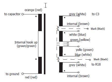
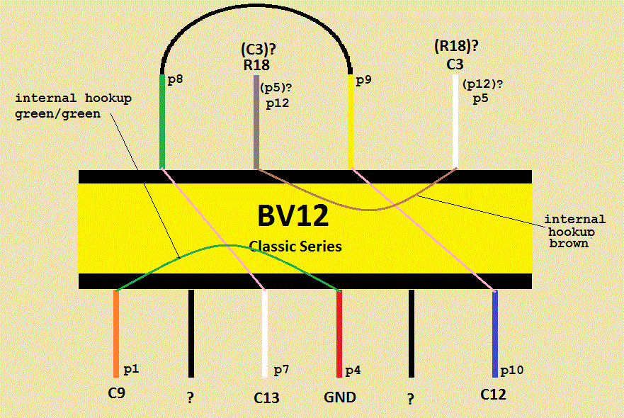
I am trying to get my head around the AMI BV12 classic transformer  connections and I have a few questions. I hope you will take pity on me and give me some pointers. First of all, does my general diagram make sense, and have I made any errors in my assumptions?

AMI's schematic:
AMI_BV12Schemeatic_zps9f580994.jpg


My diagram of the AMI BV12:
BV12diag_zps16074ff4.gif


As mickdundee63 noted earlier in this thread,  the AMI schematic differs from the actual transformer in that the AMI schematic shows  two grey wires and one white wire, whereas the actual transformer has two white wires and one grey wire. As he noted, white wire (G) has continuity with green wire (A), so it would seem that the other white wire is one of the ones marked as grey on the AMI schematic.

Question: Which destination should grey wire(B) be connected to? R28 or C3 ? This would indicate  where white wire (D) should go.
Question: What are the 2 black wires (F and I) for, and where should they be connected in the circuit?

Any help would be appreciated.

Regards,
Richard
 
rjuly said:
I am trying to get my head around the AMI BV12 classic transformer  connections and I have a few questions. I hope you will take pity on me and give me some pointers. First of all, does my general diagram make sense, and have I made any errors in my assumptions?

AMI's schematic:
AMI_BV12Schemeatic_zps9f580994.jpg


My diagram of the AMI BV12:
BV12diag_zps16074ff4.gif


As mickdundee63 noted earlier in this thread,  the AMI schematic differs from the actual transformer in that the AMI schematic shows  two grey wires and one white wire, whereas the actual transformer has two white wires and one grey wire. As he noted, white wire (G) has continuity with green wire (A), so it would seem that the other white wire is one of the ones marked as grey on the AMI schematic.

Question: Which destination should grey wire(B) be connected to? R28 or C3 ? This would indicate  where white wire (D) should go.
Question: What are the 2 black wires (F and I) for, and where should they be connected in the circuit?

Any help would be appreciated.

Regards,
Richard

please send a email to [email protected] to ask for a corrected datasheet and clarification for your question
and please post your findings here ,
thanks,
Dan,
 
Back
Top