You are using an out of date browser. It may not display this or other websites correctly.
You should upgrade or use an alternative browser.
You should upgrade or use an alternative browser.
Neumann U67 Clone : D-U67 Tube Microphone Build Thread.
- Thread starter poctop
- Start date
Help Support GroupDIY Audio Forum:
This site may earn a commission from merchant affiliate
links, including eBay, Amazon, and others.
poctop said:I have just spoke with Dennis at AMI andhe is looking into it ,
Best,
Dan,
Dany,
Many thanks for that. I have also sent an email to the support team as you suggested. Hopefully they will come back with something.
Regards,
Richard
- Joined
- Jul 15, 2009
- Messages
- 2,306
rjuly said:poctop said:I have just spoke with Dennis at AMI andhe is looking into it ,
Best,
Dan,
Dany,
i should be getting back today with a full configuration diagram for the bv12 classic series,
stay tuned,
Dan,
Many thanks for that. I have also sent an email to the support team as you suggested. Hopefully they will come back with something.
Regards,
Richard
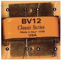
AMI sent me the updated schematic with these details below.
The circuit:
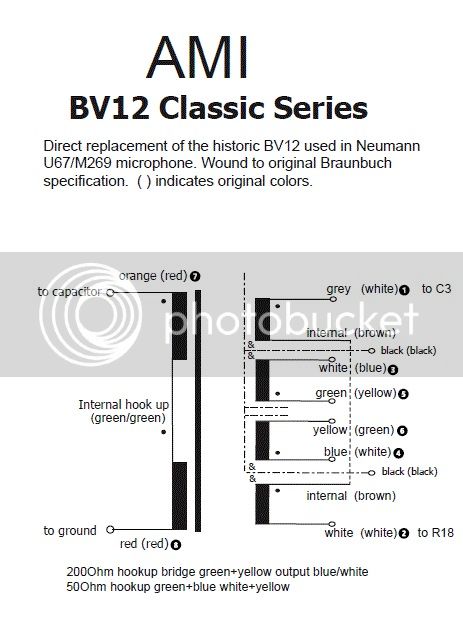
... and the reference image:
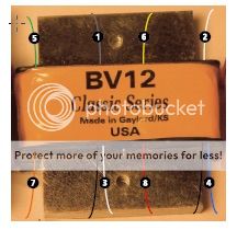
... still wondering if anyone here can tell me what the black wires connect to? Not sure what the dotted-dashed line with the "&" symbols in the circuit diagram denote.
Best,
Rich
The circuit:

... and the reference image:

... still wondering if anyone here can tell me what the black wires connect to? Not sure what the dotted-dashed line with the "&" symbols in the circuit diagram denote.
Best,
Rich
- Joined
- Jul 15, 2009
- Messages
- 2,306
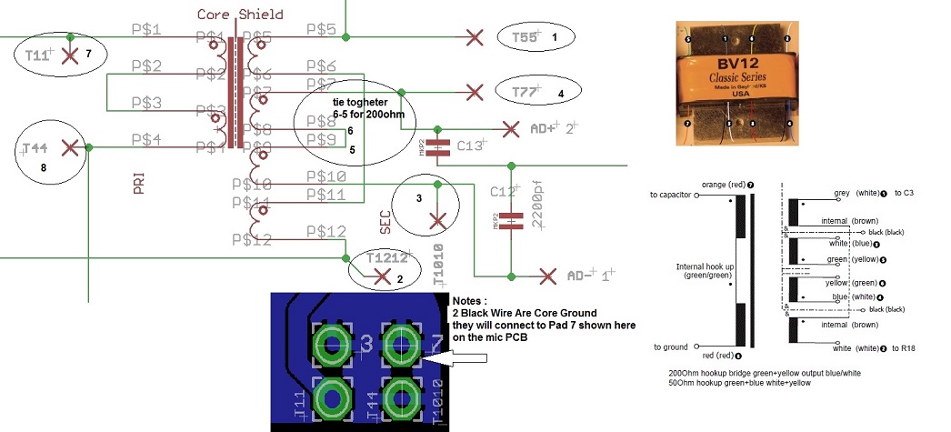
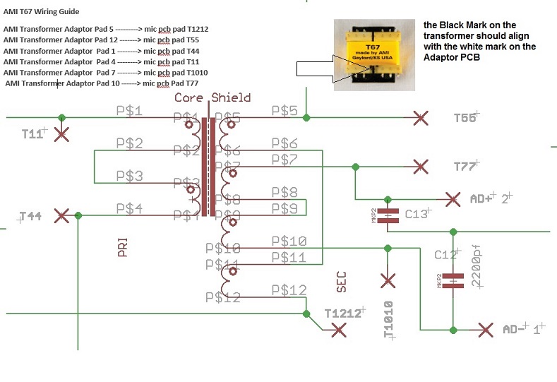
rjuly said:Here is the correspondance on the pcb pad for the U67 Mic pcb

AMI sent me the updated schematic with these details below.
The circuit:

... and the reference image:

... still wondering if anyone here can tell me what the black wires connect to? Not sure what the dotted-dashed line with the "&" symbols in the circuit diagram denote.
Best,
Rich
yes i got it this morning , cant wait to start a new build with this traffo. i really like my D-EF47 with the BV8 classic series.
let get this bv12 classic series going
the 2 black wire are actually shiedling of the core, take those 2 wires to a gnd pad onm the pcb,
Also note that the Blue wire (4) is the +audio out and the White (3) is - audio out
https://cdn.groupbuilder.com/groupdiy/u/39511/58d02819944ac.pdf
best,
Dan.
Yes, I'm looking forward to getting back to work on my pair. I have looked at my finances, and I can't afford to rectify the error I made ordering the ioaudio bv.12 version pcb's. I am going to try and make them work if possible, with the AMI bv12's. I believe they will just fit in the mic bodies I have. When I drill the holes in the pcb to attach the trafo, should I try to avoid the ground plane or try to intersect it?
Regards,
Rich
Regards,
Rich
- Joined
- Jul 15, 2009
- Messages
- 2,306
just put a small layer of large heat shrink tube under the core that sit on the pcb ,rjuly said:Yes, I'm looking forward to getting back to work on my pair. I have looked at my finances, and I can't afford to rectify the error I made ordering the ioaudio bv.12 version pcb's. I am going to try and make them work if possible, with the AMI bv12's. I believe they will just fit in the mic bodies I have. When I drill the holes in the pcb to attach the trafo, should I try to avoid the ground plane or try to intersect it?
Regards,
Rich
that will do it and give a little extra dampening effect,
Best,
Dan,
micaddict
Well-known member
Very curious how it compares to the T67.
JessJackson
Well-known member
Thats exactly how I said to wire it.
saint gillis
Well-known member
Hey Dan,
Here the voice has been recorded with a D-U67
https://www.youtube.com/watch?v=D1Q5n5KGic8
Hope its not bad publicity ! ;D
Here the voice has been recorded with a D-U67
https://www.youtube.com/watch?v=D1Q5n5KGic8
Hope its not bad publicity ! ;D
- Joined
- Jul 15, 2009
- Messages
- 2,306
saint gillis said:Hey Dan,
Here the voice has been recorded with a D-U67
https://www.youtube.com/watch?v=D1Q5n5KGic8
Hope its not bad publicity ! ;D
Love it , the song is very cool, influential work indeed, thanks for taking the time to post this , I really love the vocal track
Best,
Dan,
saint gillis
Well-known member
AMI Transformer + capsule from TSKGuy ! 
potstweaker
Member
- Joined
- Oct 17, 2012
- Messages
- 15
finally getting around to finishing this mic build. however i cannot for the life of me figure out how to hook up the capsule. any pics that could help?
- Joined
- Jul 15, 2009
- Messages
- 2,306

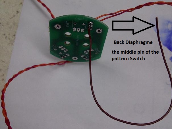
Hope this helps,
Refer to M269b build thread for pattern switch and low cut and pad,
Dan,
Yes you need to have the backplate ( metal part of the Capsule connected via a screw eylet) and then wired to middle pin of pattern switch , what i usually do is to have a pre existing lead on the switch board that goes up to the basket ,
potstweaker
Member
- Joined
- Oct 17, 2012
- Messages
- 15
what about the wire thats on the side of the capsule?where does that connect to?
- Joined
- Jul 15, 2009
- Messages
- 2,306
potstweaker said:what about the wire thats on the side of the capsule?where does that connect to?
Where the arrows point in the pictures
Dan,
potstweaker
Member
- Joined
- Oct 17, 2012
- Messages
- 15
sorry, I suppose my confusion lies in which is the backplate......would i be safe in assuming that is what the cable thats screwed onto the side of the capsule would be?
- Joined
- Jul 15, 2009
- Messages
- 2,306
potstweaker said:sorry, I suppose my confusion lies in which is the backplate......would i be safe in assuming that is what the cable thats screwed onto the side of the capsule would be?
The metal portion of the capsule is the backplate,
the gold film portion of the capsule are the diaphrgames,
hope this helps,
Dany,
Similar threads
- Replies
- 16
- Views
- 2K
- Replies
- 94
- Views
- 13K
- Replies
- 33
- Views
- 8K
- Replies
- 114
- Views
- 36K
Latest posts
-
-
-
-
[BUILD] New FET/RACK Official Help Thread - Please read first post!
- Latest: thelivingroom
-
-
-
-


