Neumann Vintage U87 Clone : Build Thread.

GroupDIY Audio Forum

Help Support GroupDIY Audio Forum:

This site may earn a commission from merchant affiliate links, including eBay, Amazon, and others.
doqmemory said:
Yes, I got the [budget YT5][https://store.studio939.com/product/budget-yt-body-kit], which has the switch graphics, but I don't think the nice brass one is in stock yet.  The graphics are easy to print on waterslide decal paper, in a pinch.

Cool, thanks.

Yeah, I wanted the nicer brass ones when I did my build, so I ended up having to go elsewhere.
 
dachmanaudio said:
Hey Matadaor! I hope this isn't a silly question, but how does one go about calculating Vgs at 1% Idss

I can do the Idss measurement no problem, but am not sure I understand the Vgs at 1%. 

Any help is much appreciated, thank you!

Best
J
IDSS is the saturation current when the potential between the gate and source are the same (e.g., both grounded).  We typically use 9V or 10V on the drain to measure this.  Let's say for example on a particular JFET this is 10mA.

VGS @1% IDSS means "What gate-source voltage causes the drain current to equal until it's 1% of IDSS".  So 1% of 10mA is 0.1mA, or 100uA.  You lower the gate voltage (down from ground, keeping the source grounded) until the drain current falls to 0.1mA.  This gate-source voltage measured when the drain current is 0.1mA is VGS @1% IDSS.  It's considered "reasonably close" to the VGS(off) for that JFET.

 
dachmanaudio said:
But, how do I lower the gate voltage down from ground while keeping the source grounded? 
You need to make it negative with respect to the source.  You can do this with a pot across another 9V battery (connect the second 9V battery + to the source (aka. 'ground')), and then put a 100K pot across the battery, and feed the gate from the middle of the pot.  This will let you dial between 0V and -9V on the gate.

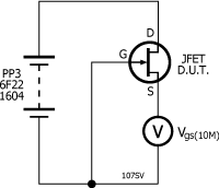
Or, you can just put a meter, in voltage mode, between the source and 'ground', and you can use the high impedance of the meter to measure very close to VGS(off).  The meter is 'V' in the diagram below.

107SV.png


If the meter impedance is 10M, then the source will float up to whatever VGS flows approximately 9V/10M = 0.9uA, which is very tiny, and very close to VGS(off) (remember VGS(off) is the voltage at which no current flows, and 0.9uA is approximately equal to 'zero' current). :)
 
I've always considered Vishay to make very good sounding, very high quality resistors. I've never used or even heard of TE connectivity, which doesn't mean they're bad.
 
I have 2 lots of 20 2n3819s i bought from Mouser (Central Semi) and eBay (Fairchild... possibly),  the  Central Semis all measure between 16 and 19mA IDSS when  testing using a 9v battery and multimeter set to mA, and the eBay 'Fairchild' fets all measure between 13 and 16mA (marginally better but still nowhere near the numbers people have talked about in this thread....).

I tried the mic with one of the lowest IDSS values from the  fets from mouser and it seemed to work, although the gain required to get much volume out of it was rather a lot, and the lowest value from the ebay fets also seems to work, however when i popped a few of the fets into my transistor tester both reported as actually being jfets but the values reported by it were wildly different between the two sets of transistors - i have attached a picture of the transistors and the values the tester shows - could someone give me some insight into why the values are so different? Im assuming it might be because the 'Fairchild' fets are perhaps not what they are labelled as!

As far as the gain is concerned to get a usable level out of the mic at a regular speaking volume - i tried with two interfaces, a focusrite 2i2 - this needed the gain turned up full and still comes out low, and a Audient ID44 which gets about the same level at 3/4 way round the gain knob, does this seem right?


Attachments

  • 2n3819.jpg
    2n3819.jpg
    273 KB
frasermunro said:
I have 2 lots of 20 2n3819s i bought from Mouser (Central Semi) and eBay (Fairchild... possibly),  the  Central Semis all measure between 16 and 19mA IDSS when  testing using a 9v battery and multimeter set to mA, and the eBay 'Fairchild' fets all measure between 13 and 16mA (marginally better but still nowhere near the numbers people have talked about in this thread....).

Those numbers seem incredibly high. I bought some really questionable 3819's from a supplier and these were the worst I had ever seen, but were still below those numbers. Check to make sure you're doing that test properly.

I was thinking about buying some of the ones from Central Semi when Mouser had them in stock a few months ago (edit, looks like they have almost 9k in stock right now), but didn't. But I did buy some from On Semi last year, and while they don't test as well as my vintage Motorolas or Fairchilds (the Fairchilds regularly had IDSS's in the 2.3 to 2.9 range), they all were under 8 or 9 and would have been usable in this build (from what I have read).
 
Thanks Ricardus,

Pretty sure i'm measuring right! I used this technique - https://cdn.groupbuilder.com/groupdiy/u/39511/58d1402a02141.jpg

Ive attached a picture with a random pick from each batch, the fairchild version appears to be pin order SGD rather than DGS, hence why the left picture is pin 1 & 2 together, and the right is pin 2 & 3 together

Tried with a brand new battery as well, not much change in values!
 

Attachments

  • idss_values.jpg
    idss_values.jpg
    541.9 KB
I thought lower idss meant less gain, but less noise and more headroom, and a higher idss was the reverse of that, unless ive misunderstood somewhere

i still think even with the high idss fets i have the mic seems to be outputting way lower than what i think it ought to
 
I'm new to the diy scene and i have two questions,

can the 330k ohm resistor (R13) be substitute for this:
https://www.mouser.com/ProductDetail/594-5043ED330K0F

i dont want to wait for them to come back in stock at mouser

and

does anyone know where i can get just one 63v 10uF cap (C12)
i dont really want  to have to order 50 from mouser
 
uptownsquash said:
I'm new to the diy scene and i have two questions,

can the 330k ohm resistor (R13) be substitute for this:
https://www.mouser.com/ProductDetail/594-5043ED330K0F

i dont want to wait for them to come back in stock at mouser

and

does anyone know where i can get just one 63v 10uF cap (C12)
i dont really want  to have to order 50 from mouser

That resistor is fine, and try this capacitor:

https://www.mouser.com/ProductDetail/Vishay-BC-Components/MAL203038109E3?qs=4T%252B5yYZyZYee5Zk%252BsfMHmw%3D%3D
 
Ricardus said:
This thread has said you usually want an IDSS under 10, but I don't understand the theory.
All other things being equal, gain will be maximized when the quiescent current is close to IDSS.  Since the U87 operating point is about 0.7mA, you want the lowest IDSS that comes close to this value (if maximizing gain is your aim).  There is of course a tradeoff between gain and input signal swing, so you need to choose between the two depending on how you'll use the circuit.
 
Hello, I’m a novice builder mainly a hobbyist. I have ran into to an issue with my build, I’m calibrating the voltage drain and the measurement for voltage I’m receiving is 0.39 maximum. Confused on where to go or what the issue is. I also have no capsule connected.  So I fixed the problem and got 11.5 volts. I installed the capsule and now I’m not getting any sound. I’m using an ami t13, so I’m going to there I guess.
 
Hi ,

I finished my U87 with  a rk-87 capsule and AML 13 transformer yesterday. It works fine , but compared to my original u87 from 1978 it seems to have lower output. Does anybody know what might be the cause for that ?
When i calibratet the drain of the fet i wasn´t abel to adjust it higher than 10,5v and not 11,5V. Might this be the problem or is it just fine ?
 
I actually testet it further now. I finished it a bit late last night, so I tested it very quickly.

It seems to have the excact same output as the original u87. The orginal U87 is a tad duller , but that might be that the capsule is dirty.
 
I'm ordering the BOM and I was wondering if for C15 I can order Styroflex of 620pF 160V instead of 560pF 630V or keeping the voltage and capacitance straight on styroflexes is important

I was thinking of order them at Don-Audio instead of Mouser since they are located in Europe and I can´t find the substitutes I have for styroflexes (Wima FKP2 560p/100V/5mm,Ero KP1830 470pF/100V/5mm, etc):

560pF/630V  (Styroflex 620pF https://www.don-audio.com/Styroflex-Polystyrene-Film-Audio-Capacitors_3)
470pF/630V (Styroflex 430pF https://www.don-audio.com/Styroflex-Polystyrene-Film-Audio-Capacitors_12)
10pF/630V (https://www.don-audio.com/Styroflex-Polystyrene-Film-Audio-Capacitors_19)
220pF/630V (https://www.don-audio.com/Styroflex-Polystyrene-Film-Audio-Capacitors-220pF)

https://www.don-audio.com/Styroflex-Polystyrene-Film-Audio-Capacitors

Would these do the job?


Thanks all!
 

Latest posts

Back
Top