kepeb said:ok, i give up.
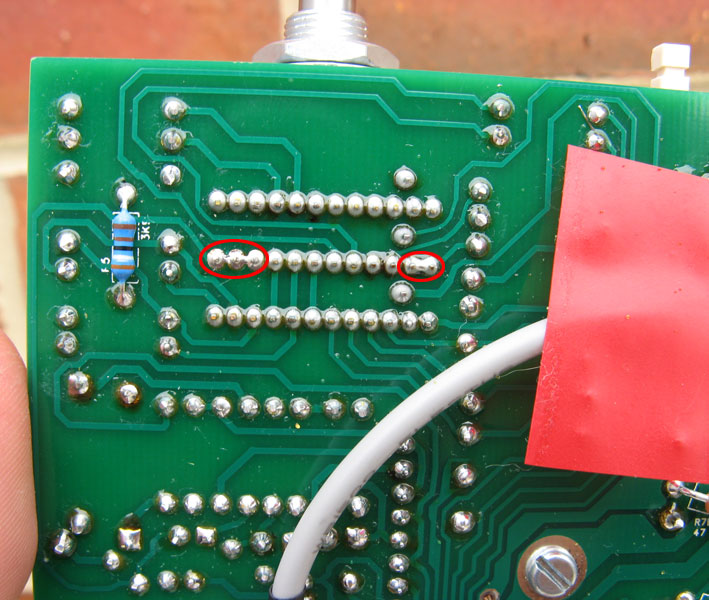
I wont be getting those relays, i'm 24v and i will do as you say onlymee and just jumper them.
someone kind enough to hold our hands and point out the exact jumper positions on a picture for us?
cheers")

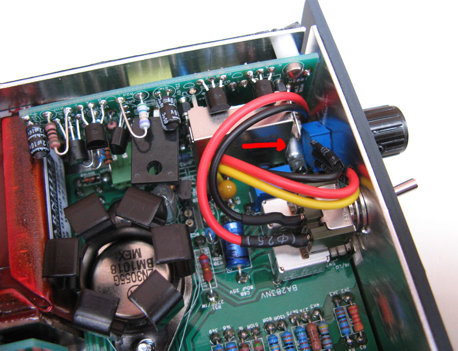
@jandoste... Good work!!!! Looking good. Just a few things to do really before on, the main thing being the trim pot is completely counterclockwise to start with http://www.thedonclassics.com/nv73manual.html
@canidoit.. the BOM (googledoc) has always been correct.. the only thing that went wrong with the mouser cart was that the out of stock items at the time were removed. instead of showing up as backordered. Fixed now.
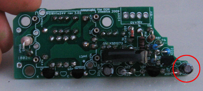
psC4 is in the googledoc. It's needed for power supply ripple. Any 100uF (there abouts) 25V will do (as long as it fits physically) 6 mm Dia. x 10 mm L mouser says it is.
In the pic I hadn't finished all soldering.. just wanted to make clear to solder the bottom of the DC-DC converter parts before putting in the DC-DC converter.. so you have the option of just leaving the DC-DC converter in the sockets on the board without needing to 'get at the underneath' If that makes sense.. Not a big deal either way. That's what the sockets are for after all
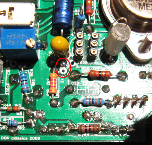
There's a couple of high res pictures of the PCB silkscreen I posted a couple of pages back to check any references/part values.
The middle 2 legs don't do anything for this circuit so I just leave them hanging
either that you have for sockets is fine.. I like to keep the 6 space ones for transistors tho.. A 6 space is less fiddly to fit than two 3 spaces.
EDIT... updated incorrect picture.
![Electronics Soldering Iron Kit, [Upgraded] Soldering Iron 110V 90W LCD Digital Portable Soldering Kit 180-480℃(356-896℉), Welding Tool with ON/OFF Switch, Auto-sleep, Thermostatic Design](https://m.media-amazon.com/images/I/41gRDnlyfJS._SL500_.jpg)