You are using an out of date browser. It may not display this or other websites correctly.
You should upgrade or use an alternative browser.
You should upgrade or use an alternative browser.
Neve style 500 series mic pre 1290 1073
- Thread starter onlymeeee
- Start date


Help Support GroupDIY Audio Forum:
This site may earn a commission from merchant affiliate
links, including eBay, Amazon, and others.
Neil
Well-known member
It's entirely probable that I missed this in the build documentation but I've got two holes not connected, one labeled TP2 Chassis by the 2N3055 and the other that says GND 0v by the phase pushbutton. Should they be connected somewhere?
shabtek
Well-known member
tp2:
test point?
setting bias?
test point?
setting bias?
Neil
Well-known member
That occurred to me but I thought you set the bias right from the case of the 3055?
Neil
Well-known member
Ok thanks. So I'm going through the tests before powering on, and testing from both pin 1 of the output transformer to the 0v gnd TP and pin 3 to the same point my Fluke 87 settles out after a long while at about 15k. This is without any transistors socketed. Problem? It's certainly not off the scale. The trimpot is fully cc.


![Electronics Soldering Iron Kit, [Upgraded] Soldering Iron 110V 90W LCD Digital Portable Soldering Kit 180-480℃(356-896℉), Welding Tool with ON/OFF Switch, Auto-sleep, Thermostatic Design](https://m.media-amazon.com/images/I/41gRDnlyfJS._SL500_.jpg)


Neil said:Ok thanks. So I'm going through the tests before powering on, and testing from both pin 1 of the output transformer to the 0v gnd TP and pin 3 to the same point my Fluke 87 settles out after a long while at about 15k. This is without any transistors socketed. Problem? It's certainly not off the scale. The trimpot is fully cc.
Should be OK, it's only if it's a low reading that it would signify a fault., eg. you're testing the 24V rail, so a short to ground.. would be bad!
Neil
Well-known member
desun said:For the board to fit into an API lunchbox (+/- 16v), there needs to be a little physical modification to the board where the 51x pins are-- the gap needs to be larger, otherwise it won't fit in. I don't want to cut them off as i'll be moving to 51x in the future")
Yes, and I found out tonight that you also have to file about 2-3 mm off the ends of the two 51x pins if you want the module to sit down flush in the lunchbox. The pins are a little too long for the shoulder edge of the connector inside on the motherboard to allow it to seat all the way otherwise.
onlymeeee said:I originally designed as an 'either' rather than swappable, and as such, used the old trusted 'cut em of' method.
However, I did think about the possibility of making the gap a bit bigger, (forego the -24V rail) and then you wouldn't need to cut the +24V rail off to fit in the +-16V lunchbox.
After making the gap bigger... do you feel the +24V finger now is a bit compromised/not as physically strong, or is it ok? That was the only thing stopping me from just going ahead with it. (But I'm probably over-paranoid!)
I don't feel that the strength is compromised. And once it's screwed down into the lunchbox it's not going anywhere anyway.
kepeb
Well-known member
would it be unwise to use a thermistor as a jumper in place of the relay for 51x 24v operation?
kepeb said:would it be unwise to use a thermistor as a jumper in place of the relay for 51x 24v operation?
I wouldn't use a thermistor. Just jumper, it'll be fine.
What is going on with the psC4 - 100uf 35v cap on the small PCB?
On your Manual, it does not have it in the pic, in your BOM and cart it's not listed to buy but in your video, you can see the blue cap where it is positioned and also printed on the small PCB.
Since I was unable to purchase it because it was not in the shopping cart or BOM, do I need to use it for my 16volt version of this build. If it is a must, are there any alternatives?
Is this how we are meant to position the sockets for the TDK

Because there are the other 2 legs that you haven't put the socket on and then there's holes on the PCB for those 2 legs??
It doesn't look like those 2 leg holes are going anywhere on the PCB board but I want to confirm incase there is a reason you have placed those holes?
Because there are the other 2 legs that you haven't put the socket on and then there's holes on the PCB for those 2 legs??
It doesn't look like those 2 leg holes are going anywhere on the PCB board but I want to confirm incase there is a reason you have placed those holes?
Neil
Well-known member
I soldered and placed the DC converter exactly like the picture shows. You can also see the orientation in the video of how the boards go together. The legs that aren't soldered in the picture I didn't bother with. Seems to work fine, although I haven't run any audio through my units yet, just calibrated.
I think the pic was taken before all components were soldered. There's a note that says psC4 - 100uf 35v cap can be a 25v cap since it never sees higher than that from the converter. I used a 25v 100uF since it was smaller.
canidoit said:What is going on with the psC4 - 100uf 35v cap on the small PCB?
On your Manual, it does not have it in the pic, in your BOM and cart it's not listed to buy but in your video, you can see the blue cap where it is positioned and also printed on the small PCB.
Since I was unable to purchase it because it was not in the shopping cart or BOM, do I need to use it for my 16volt version of this build. If it is a must, are there any alternatives?
I think the pic was taken before all components were soldered. There's a note that says psC4 - 100uf 35v cap can be a 25v cap since it never sees higher than that from the converter. I used a 25v 100uF since it was smaller.
jandoste
Well-known member
finally finished them ! and I bought an API Lunchbox (6) ! Because I must work now ) next year I will try to build 51X !


So I need to do testing them before putting to API lunchbox ?
Was so easy build Mr David !
Thanks again !
Cheers,
) next year I will try to build 51X !

So I need to do testing them before putting to API lunchbox ?
Was so easy build Mr David !
Thanks again !
Cheers,
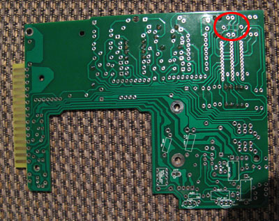
Can someone please tell me the part number and resistor resistance of the part outlined in red in the pic.
eg. R21, 1K5...
The printing was not clear on the PCB board and it's hard to distinguish exactly what is written on the board.
Thanks
eg. R21, 1K5...
The printing was not clear on the PCB board and it's hard to distinguish exactly what is written on the board.
Thanks
jandoste
Well-known member
canidoit said:Can someone please tell me the part number and resistor resistance of the part outlined in red in the pic.
eg. R21, 1K5...
The printing was not clear on the PCB board and it's hard to distinguish exactly what is written on the board.
Thanks
R5,3K9
cheers,
kepeb
Well-known member
ok, i give up.
I wont be getting those relays, i'm 24v and i will do as you say onlymee and just jumper them.
someone kind enough to hold our hands and point out the exact jumper positions on a picture for us?
cheers
I wont be getting those relays, i'm 24v and i will do as you say onlymee and just jumper them.
someone kind enough to hold our hands and point out the exact jumper positions on a picture for us?
cheers
Similar threads
- Replies
- 24
- Views
- 7K
- Replies
- 8
- Views
- 4K