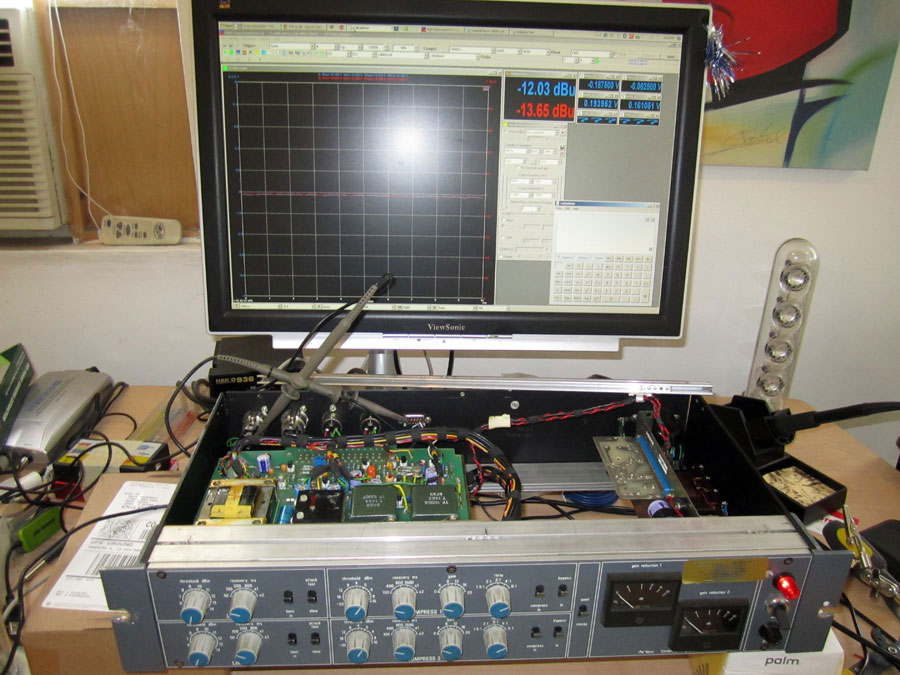
Official 33609 builder's tread. See 1st page for updates.

GroupDIY Audio Forum

Help Support GroupDIY Audio Forum:

This site may earn a commission from merchant affiliate links, including eBay, Amazon, and others.
Thanks for the reply, I have used those, they do not hold very well in this kind of application... I find it needs a few pins soldered in to keep it from coming loose, rather defeating the purpose.
 
I used them in my 33609 and it's been fine for about 2 years now.  Maybe I just got lucky with some tight fitting ones.
 
I get a little hum from my monitors, like from a ground loop, when I turn on my 33609. This is when the 33609 isn't being monitored, but just plugged into the patchbay and connected to different i/o of my soundcard.
Currently, the XLRs pin1 goes to chassis, wire shielding, and then the pad on the pcb. I'm thinking the shield should possibly be disconnected from the pcb. But I haven't really examined the pcb to figure out the ground scheme. My understanding is chassis/shielding should not connect to audio ground (I just re-read the Rane 101 tech note). But I'm not sure if the pcb is set up with a ground plane separate from audio ground. Anybody else have advice on this?
Igor, I'd be curious if you could describe the grounding principles you use for this pcb design and your recommendation for proper wiring. 

By the way, the 33609 does not get any hum when used, it just causes my monitors to hum when turned on.
Thanks, Dan


I found the same solution as Curtis earlier in the thread:
I found that I got the quietest operation by linking the two grounds on the PSU together.
The audio ground doesn't have any connection to the chassis ground on the PSU pcb. I added a wire to connect the audio ground on the PSU pcb to the chassis star ground point. No hum anymore.
I think it is standard to connect the audio/power ground to earth - I don't know if there is any reason not to? Anyway, this is a solution for hum.
 
Hi , just got to work on my 33609  after a 2 year diy-out..
have some problems at sourcing the right relay :'(
farnell say 70 days delivery time for the relay igor mentioned ( 9913653 )
would this one  be ok ,seems to have other dimensions?
http://de.farnell.com/tyco-electronics/fx2-d3227/leiterplattenrelais-dpco-24vdc/dp/9913939

do i need 2 or 4 relays?
thanks
axel
 
You don't have to use the exact part number that Igor posted.  A 24V DPDT relay in a DIL case is extermely common and available just about anywhere from many different manufacturers.

2 relays per channel - 4 total.
 
Ok, its not to pricey also, will try them.
Hey Igor, you prefered a hi-b trunny for output, do you want to share specs ?
I am in contact with Sowter, they would make a trunny for me if i can give them more infos..
greets
axel
 
OK, now this is a more technical question :
i have a whole bunch of nice dale resistors i would like to use in this project, as
they are not always the E10 range i am off in some values,  in the worst cases maybe 8 to 10 percent.
I don´t think this is critical as in the older times the specs were more loose
and we have some trimmpots around?
(in the lower range they differ more but in the gain/tresh/makeup area it does not mind me if it is not 0.5 db
but 0.6 or so )
so just want to ask if there is a place where i have to go 1% spec (not mentioning the PSU)
thanks again
axel
 
so just want to ask if there is a place where i have to go 1% spec (not mentioning the PSU)
Everywhere in my opinion. You are talking about saving maybe $10-$20 by using the wrong value resistors - does not make any sense at all. Get high quality 1% metal film resistors and build a great piece of equipment. The whole basis of the compression occurs symmetrically on the balanced signal so slight differences in resistors could unbalance what is a really great design.  Even in non-critical places I would not cut corners this way.


the vishay dales are 0.5% to 1% and i have enough to even match further..
so no sym or channel related probs expected here..
the basic values are not always E10 range so some of the values are off right from factory
i.e.3k57 maybe is 3k62 (don´t have them handy right now)
they are nos non magnetic ones for audiofullery fun so i don´t really save a buck here ;)
so i hope i can take them for this hopely wonderfull project !
ax
 
Hi All,

This might be an interesting piece of info for all of you who have the unit built or thinking about building one. A few days ago I decided to get an original 33609 (the original version, with Marinair transformers, back from 1988) to settle (literally) once and for all my debate about whether or not the DIY version has the same/similar time constants and frequency response, because they don't sound the same to my (and many others') ears. This time (as opposed to back in 2008, where I only did listening comparisons between the two - see pages 19-21-ish...) I actually had the tools to measure the attack/recovery behavior, as well as to sweep the units and do some THD/SNR tests. Here is what I found out:

The compressor recovery time constants are nearly identical between the units, but the attack on the original is noticeably slower (which I could identify by listening to both units, not just measuring) - 25ms, vs DIY's 15ms. I modified one of my DIY units with replacing R31 with 1k1, which brought it to about 22ms. I suspect somewhere around 1k2 or 1k3 there would make it closer to original's attack response. There is virtually NO info on the internet about 33609's compressor attack time. The only page I found had 40ms listed... which seemed a bit too long.

I also modified the compressor recovery settings to bring them closer to the label values on the front panel. Initially both the original and DIY had 70ms measured recovery @ 100ms switch position, 285ms @ 400ms, 600ms @ 800ms, etc... I replaced 24k with 33k, which made the 100ms position exactly 100ms, and 75k with 100k, which made the 400ms position exactly 400ms. It, of course, shifted the rest of the recovery settings to release slower (850ms and 1800ms) which I really like.

Now the limiter section is where things got hairy... My DIY unit measured exactly 2ms on fast attack settings and 4ms on slow attack - 100% dead on within specs. The recovery times were exact too - 55, 120, 240, 1000, 2300, 6000 at each switch setting. The original measured waaaay slower - attack times were doubled (??) - 4ms on fast, 8ms on slow. The recovery times were noticeably slower as well - 80, 165, 330, 1300, 3350, >7sec. Does that mean it needs a recap? =) I'm not sure, but I'm sure that was the reason for limiter to behave a lot smoother in my listening tests on the same settings as the grainy distorted DIY version.

So, the above info revealed to me that overall the DIY unit measured closer to Neve specs, but how does it SOUND? =) I'm yet to acquire a definitive conclusion on that topic after I run it through some listening tests in the next couple of weeks and maybe take it to big commercial studios to be checked out in that setting.

The thing that still bugs me a bit about the DIY version is its inability to calibrate the meters exactly. The original has it pretty dead on in 0-20dB range, while the best thing for the DIY version is to calibrate it exactly at 8dB reduction. Then it drifts upwards when applying more reduction (i.e. 12dB CV will show as 13-14dB on the meter) and downwards with less deduction (i.e. 4dB CV will show 2-3dB on the meter). Any solutions to that?

Thanks for reading! =)
 
Interesting results. I'm assuming your comparing it to the original issue, metal knob 33609.

Curious, how you measured the times and also to see comparative images of your findings if you have them.

I have my 33609 populated with original Marinar iron right out to the output transformers and some additional tweaks that are truer to the original. I'd be curious to run some tests (analytical/listening) on mine to compare to your results.

Mark
 
Biasrocks said:
Interesting results. I'm assuming your comparing it to the original issue, metal knob 33609.

It is the original (i.e. prior to "C" edition), however it doesn't have metal knobs anymore, but the internals are still identical (same EV10475 boards). Here is a picture:

original33609_calibration.jpg


I do have some screenshots of measurements, I will post them a bit later.


I actually had the tools to measure the attack/recovery behavior

I am very interested to know how you measured the attack and release times.
What I did was make a recording of a tone burst, and then zoom in to measure the envelope of the waveform.
But maybe you have an other (easier?) way of measuring this?

(I already knew that the Neve compressors sounded so good because they are slooooow....)
 
The way I measured time constants was taken from the calibration procedure. I.e. apply a test signal (10kHz for attack time measurements and 1kHz for recovery) and increase it by 10dB to measure attack, then decrease it back by 10dB to measure recovery. I.e. the recovery time for Neve compressors is assumed to be the time taken by CV to stabilize at new value while the test signal is dropped by 10dB from its previous amplitude (the opposite is true for attack measurements). The only thing I did differently from the manual was to use +6dBu and +16dBu levels instead of +10 and +20 as stated in the calibration manual. However difference that might have made it's not that important for my measurements as I was more concerned with RELATIVE difference between the original and DIY units and not absolute measurements. And I'm pretty sure the actual difference is not that significant as both level differences are 10dB. Anyway...

ORIGINAL 33609 time constants:

COMPRESSOR ATTACK @ 100ms recovery, 6:1 ratio, -20dB threshhold, 10kHz sine
COMPRESSOR ATTACK @ A1 (100ms) recovery, 6:1 ratio, -20dB threshhold, 10kHz sine
COMPRESSOR ATTACK @ A2 (50ms) recovery,  6:1 ratio, -20dB threshhold, 10kHz sine

COMPRESSOR RECOVERY @ 100ms, 6:1 ratio, -20dB threshhold, 1kHz sine
COMPRESSOR RECOVERY @ 400ms, 6:1 ratio, -20dB threshhold, 1kHz sine
COMPRESSOR RECOVERY @ 800ms, 6:1 ratio, -20dB threshhold, 1kHz sine
COMPRESSOR RECOVERY @ 1500ms, 6:1 ratio, -20dB threshhold, 1kHz sine
COMPRESSOR RECOVERY @ A1 (800ms), 6:1 ratio, -20dB threshhold, 1kHz sine
COMPRESSOR RECOVERY @ A2 (1500ms), 6:1 ratio, -20dB threshhold, 1kHz sine

LIMITER ATTACK @ 50ms recovery, FAST attack (2ms), +4dBu threshhold, 10kHz sine
LIMITER ATTACK @ 50ms recovery, SLOW attack (4ms), +4dBu threshhold, 10kHz sine
LIMITER ATTACK @ A1 (2000ms) recovery, SLOW attack, +4dBu threshhold, 10kHz sine
LIMITER ATTACK @ A2 (5000ms) recovery, SLOW attack, +4dBu threshhold, 10kHz sine

LIMITER RECOVERY @ 50ms, SLOW attack, +4dBu threshhold, 10kHz sine
LIMITER RECOVERY @ 100ms, SLOW attack, +4dBu threshhold, 10kHz sine
LIMITER RECOVERY @ 200ms, SLOW attack, +4dBu threshhold, 10kHz sine
LIMITER RECOVERY @ 800ms, SLOW attack, +4dBu threshhold, 1kHz sine
LIMITER RECOVERY @ A1 (2000ms), SLOW attack, +4dBu threshhold, 1kHz sine
LIMITER RECOVERY @ A2 (5000ms) was over 7 seconds, no screenshot here...

FREQ SWEEP 10Hz to 96kHz @ +14.77dBu - ORIGINAL 33609
FREQ SWEEP 10Hz to 96kHz @ +14.77dBu - DIY VERSION
FREQ SWEEP 10Hz to 96kHz @ +14.77dBu - HARD BYPASS (to see linearity and LPF of audio interface)

There is a nasty peak in my audio interface at around 200Hz that throws off the relative 0dB axis by almost a dB (you can see it in all 3 sweeps on most left) - just disregard this nonlinearity. =)

On attack and recovery screenshots you can see T2-T1 label in third row above the scope display - that is the measured attack/recovery time between two test points.

Hopefully the above will be of help to others, as it was to me.
 
Biasrocks said:
I have my 33609 populated with original Marinar iron right out to the output transformers and some additional tweaks that are truer to the original.

Can you give us a little more info as to what additional tweaks you're talking about that bring it closer to the original? The only tweak I found useful to give me a closer to the original time response was to increase compressor attack time by about 10ms. The limiter section in the original seems a bit fishy to me and way off specs according to Neve's own manuals, so I didn't take time to conform my version to the original there. I'm eager to know what else I could do to make it behave closer to the original, both in time and frequency domains. What were your findings as far as original/diy differences? Thanks!
 
..so after all the time the comp is done..just output trannys missing
liking some sowter outs, mr.sowter wrote me his LO1173 replic (75/600) 1/2.83 conn. in parallel were
designed just for this comp. He would surely make me 1/2.5 Trannys if i would insist (same price..!)So i would like to
know if somebody did some measuring with the original if they are really straight 1/2.5 or more like 1/2.83 ?
even the carnhill reissue there is no info about ratio on their side
thanks in advice !
axel
 

Latest posts

Back
Top