official GDIY51PSU Help & Support Thread

GroupDIY Audio Forum

Help Support GroupDIY Audio Forum:

This site may earn a commission from merchant affiliate links, including eBay, Amazon, and others.
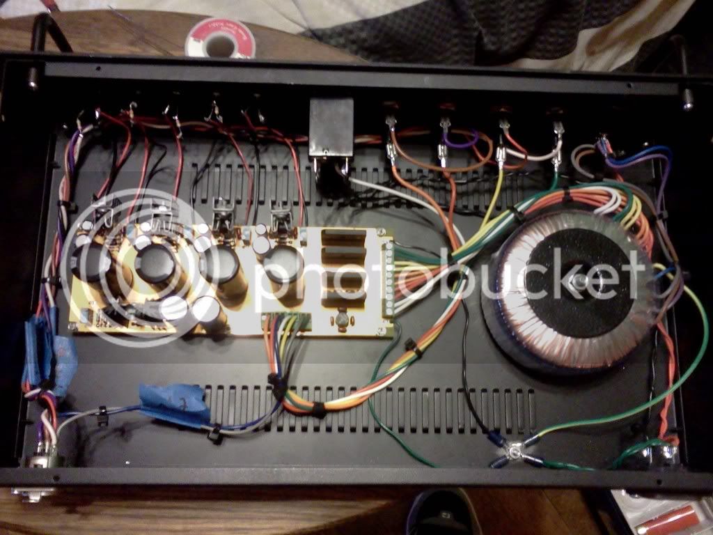
depending on where you are, jeff has posted a diagram denoting all the transformer outputs for those who have bought that toroidal in the US.

if you are in the UK there is a photograph posted somewhere that suggests the wiretaps exit the transformer in the same order they appear on the PSU inputs.

your chosen heatsink is too small to wick sufficient heat In my opinion, i would go bigger for the 16/24v rails although this is the right thread size and would fit the 48v regulator, the board mounted option is better tho.

jumpers:
if you actually using jumpers then the choice remains yours, if you dont like it change it. then change it back if you like. if i were to omit jumpers i would hardwire to ground unless you are confident you have good chassis connection from 511 to psu through your power cable.
 
What heatsink would you recommend? Or if anyone has a part number from mouser that would be awesome too. I'm not talking about the heatsink for the TL783, I have that one, I am talking about for the other 4 LM350T's.
 
all depends, from what i understand there is a limit in size to where it ceases to become effective anyway.
then theres your choice of enclosure, some have heatsinks for sides.

i didnt find one that was pre made to accommodate the four in a line like this, so i got an old one and re drilled it. four largish individual t220 stylr ones would suffice.

you may also get respectable heat transfer with just the enclosure but in any case:))), make sure they are all electrically isolated and with suitable compound etc.
 
you should.
they need to go betwixt the dc outs on the psu and the cable to your 511.

they should be rated according to what you intend to draw from that rail, 1 - 1.5Amp for the module supplies maybe...
and your mains should also be fused of course.
if you scroll back through these help threads there are several, partial discussions of this dotted around.
should only take you a few days :)


Guys,
short question regarding the Power LED's and the connection:

- i don't have seperate fuses, just a main one on the 220V.
- what resistor value do i use for each LED on the rails ?
- i assume i ground the Anode.
- Kathode via Resistor to the respective Power.

am i right with this? that is the last bit missing on my PSU assembly.

 
just use standard red 5mm
anode to ground on - rails, ground cathode on + rails
+48v = 4k7
+-24v = 2k2
+-16v = 1k5

edit: not taking credit btw, just passing it along
 
Thanks for the support. Found a mismatch (wire crossed) on my wiring. +/- 16V was crossed. Fixed now.
Assembling now :)

One thing i noticed: i have two Aphex CX-1 which hardly fit in (because of the casing). Wasn't able to test if all have contact.
The DIY modules fit all in nicely.


I'm a bit confused about wiring the transformer to the PCB. The Classic API diagram shows 2 of each color. One going to the indicated voltage and one going to 0v. Do I only use one of each wire to the board? Or do I wire one to the indicated voltage and the other to ground (0v)?
 
not quite sure what you mean here...
however, from the transformer you will be getting AC which is then rectified on the psu to DC.
you need two contacts from each transformer tap/winding to get the + - to the respective rectifier stages.
there are two connections for each on your psu pcb..

there are posts about the grounding and a diagram, you just need to apply the relevant changes to the transformer out wires on your US 51x transformer via jeffs transformer diagram.
 
Yes, correct with what kepeb has said. The 2 same color leads will go to the 2 screw connectors labeled for the same voltage.

For example, the 2 red leads will go to a pair of screw connectors that are side by side and labeled AC24V.

The 2 orange leads will go to the other pair of screw connectors that are side by side and labeled AC24V.

Hope that makes sense. It's been a long day for me.  :)
 
I have my 51x rack and PSU up and running and just wanted to give a big shout out to everyone in the alliance who made this so easy to build!
As soon as I get the bugs out of my LAZ 525's I'll be ready for my next 51x project. Any suggestions?
Cheers! ;D
 
duantro said:
I have my 51x rack and PSU up and running and just wanted to give a big shout out to everyone in the alliance who made this so easy to build!
As soon as I get the bugs out of my LAZ 525's I'll be ready for my next 51x project. Any suggestions?
Cheers! ;D

I love my classic API 312.  Jeff also has other cool DI/Mic Pre options in 51X format.

Mike
 
I've got to parallel wire the main switch since I am in the US and using 110V power and I'm little confused how to do this. You guys said to use a DPST switch, but I opted to use 2 SPST switches because I was in a pinch. This should still be cool right? I have looked at both diagrams on this forum and was still a bit confused. 

In actuality I could just use one switch but I am going to use 2 because I already cut the holes for them. One pole of the switch is connected to the hot wire from the wall (by that I mean the IEC plug), the other poll of the switch is connected to the transformer. (which is actually the 2 transformer hots tied together).  

The second switch is done the same way but with the neutrals.  All grounds are then connected via a star ground to the case. This includes ALL grounds. The chassis and ground from the PCB, the ground from the transformer, and the main IEC ground.

I'm using a breaker for the hot, do I really need one for the neutral?
 
I finally finished this weekend. I got everything tested and it seems to be all good. Thanks everyone for your patience with my questions. Also, thanks to everyone who designed this project.

121610003538.jpg

121910213615.jpg


Back
Top