official GDIY51PSU Help & Support Thread

GroupDIY Audio Forum

Help Support GroupDIY Audio Forum:

This site may earn a commission from merchant affiliate links, including eBay, Amazon, and others.
Look, for gods sake I must have had too much beer last night. I blew the 48v fuse because I didn't switch the mains off when I plugged a mod in this morning. what a twat.

M
 
New Soul Rebel said:
Look, for gods sake I must have had too much beer last night. I blew the 48v fuse because I didn't switch the mains off when I plugged a mod in this morning. what a twat.

M

Ha! There have been many occassions that I tried to read voltages without plugging the DUT to the mains. ;D


JB,

Check the boards one at a time and see what happens.
 
Ok found the problemo!

The pic and description of JamesW's PSU on page 9 I just went ahead and built it without 1 small thing. The 1/8th inch aluminum. I figured since it wasn't causing problems for his V regs being bolted to a piece of metal, then just bolting mine to the side of the case I got (same as his) would be fine.

that's a big ol negative. (Now a lot of you are slapping your forehead going "DUH!!" but hey, I'm new to all this)

Very interesting to learn that Aluminum can actually act as an insulator in this situation. (unless i'm off base)

Cheers errbody!
 
Hiya Gents,

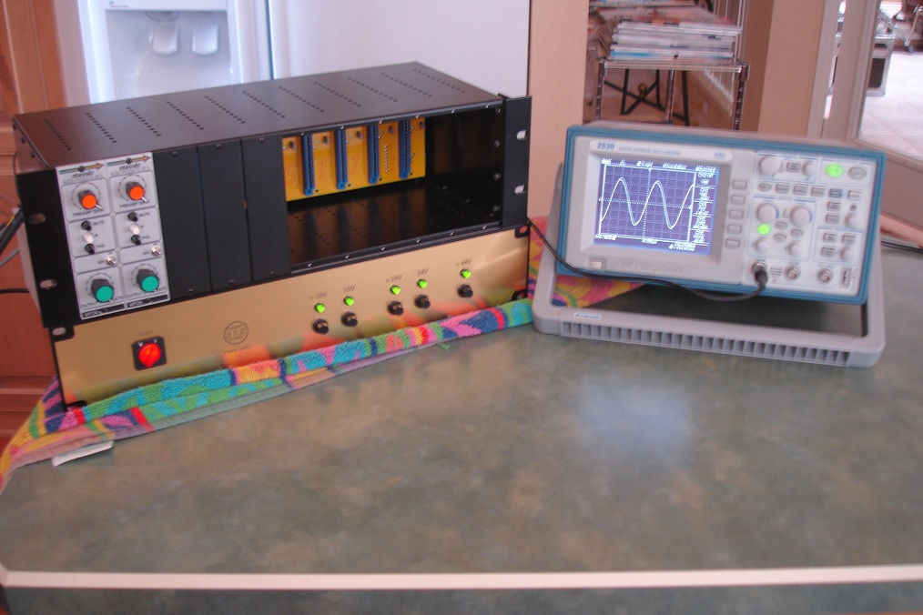
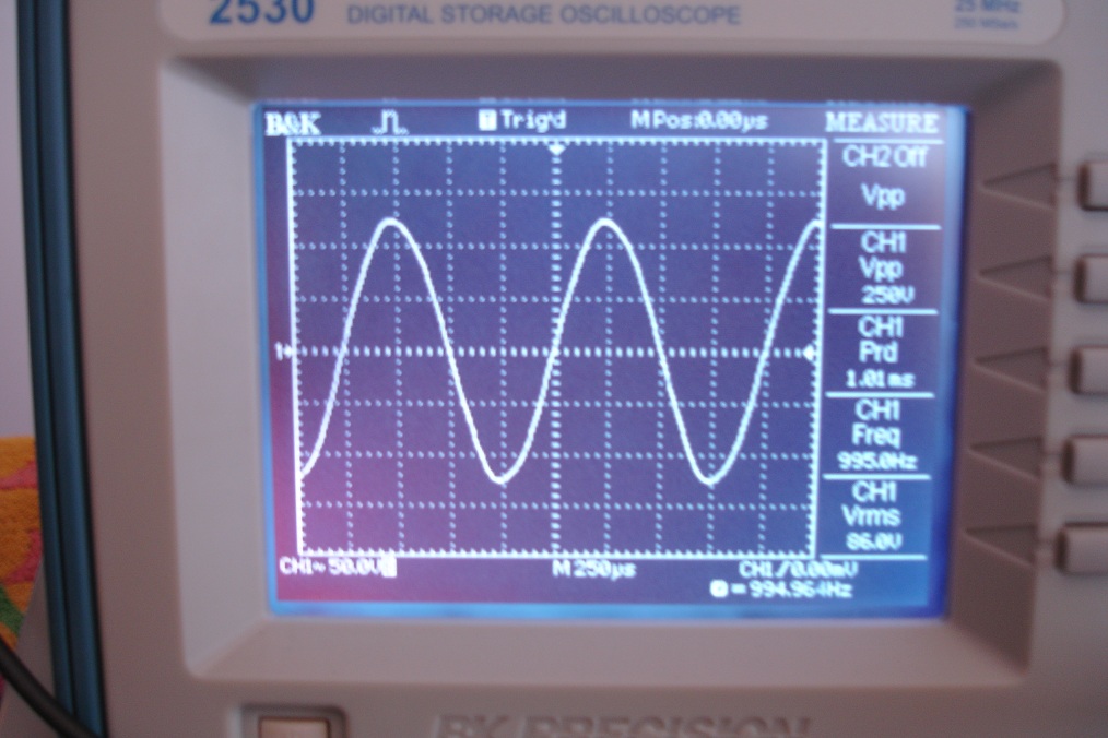
Getting back to it and my -24 was acting up, found a dry socket. Seems I'm OK. However on +48 C8 is beginning to explode, break open, and spew juice. It's weird because C6 is the one that is getting unnervingly hot (suspectedly explained some electronics that I'm just ignorant of).The Voltage would charge then discharge, never quite getting to 48V. Needless to say I shut it off.

There are no apparent physical issues to the build.

Quick question though, I do want to solve this issue, but I have absolutely no need for 48V in this rack at this time. How could I safely isolate that rail? Just leave the Vreg and/or other components off? I figure there has to be a right way to leave out 48V.

Thanks all!

JB
 
Very interesting to learn that Aluminum can actually act as an insulator in this situation. (unless i'm off base)

JB  You need to insulate the regulator from the case while  making good thermal contact. You should find what you need here  www.keyelco.com/pdfs/M55p103.pdf
 
you need to insulate all regulators, I would even add: in all PSUs!

exploding C8: are you sure you did solder it with the correct polarity ?
there is nearly no other way to get it smoke.

easiest way to disable the 48V is to not connect the 48V secondary of the PSU transformer.
 
Here is my version of the PSU.
Nothing fancy but im happy with my first self drawn (and finished!) metalwork. Most of my projects ended up in a shoebox if finished at all.
Big thanks to silent:arts, sahib, Ptownkid and zayance for their support during my journey.
 

Attachments

  • 51xPSU.jpg
    51xPSU.jpg
    390.4 KB · Views: 199
[silent:arts] said:
you need to insulate all regulators, I would even add: in all PSUs!

exploding C8: are you sure you did solder it with the correct polarity ?
there is nearly no other way to get it smoke.


easiest way to disable the 48V is to not connect the 48V secondary of the PSU transformer.

Positive. This is a new experience. It's never acted up before. Could a bad regulator do it?

I removed the 48V tails and the Cap still started bubbling. I'm guessing that would have to be a short somewhere correct?


****** Found a short in the header.... ::)******
 
Thanks to all the suppliers and the headaches in getting this together. I finally got my PSU case and parts and completed it yesterday with great results. Now, I am just waiting for more parts for modules so I can build out my rack. I have 2 VP26s now, and am looking to build some more. After tuning the PSU and hooking up the rack, I surpassed my previous headroom number on the VP26. My new output with a 1 kHz tone plug is 250 Vpp/86 Vrms! Gotta love 24V! My Studer will be crying :)


pictures kinda suck, but you get the idea...

DSC01798.JPG

DSC01799.JPG
 
kepeb said:
just use standard red 5mm
anode to ground on - rails, ground cathode on + rails
+48v = 4k7
+-24v = 2k2
+-16v = 1k5

edit: not taking credit btw, just passing it along

Thanks for this. So, one side of the LED goes to ground & the other side goes to voltage, through the designated resistor? At this point, what is the difference between chassis & ground? This ground point can be picked up off of the PCB at the solder tabs?
 
If the LED's were mounted right on the PCB where Volker has laid out for them, they would connect to the GND plane. However, since everything here is so close to the star ground point (and away from audio paths), I don't think it much matters which one you pick. Maybe I am wrong.

Cheers, Jeff
 
OK, I had success!  ;D Finished up , hit the switch and no smoke... Tweaked in all the voltages and everything is working perfectly. Only thing not working is the light inside the on/off switch. I realize this is a DPDT switch. What voltage is the light inside, and what terminals to operate it? I think I tried every combination. Does it need the neutral? If so, where to wire?
 
The switch came in the parts package along with the rack that I got through Jeff. The parts list does not indicate manufacturer or model number. The switch is visible in this photo via Jeff's website.
 

Attachments

  • Std-elec-wiring.jpg
    Std-elec-wiring.jpg
    117.8 KB · Views: 61
When viewing the switch from the inside of the case:

-top left lug is from mains fuse (AC L)

-bottom left lug goes to V select switch (AC L)

-top right is from IEC (AC N)

-bottom right goes to V select switch (AC N)

That should make her lite up all purdy. 8)
 
OK, thanks. So it needs to switch the neutral. I by-passed the voltage selector, since I'll only use it with 120Volts. Now I know what to do to make it work.
 
Hi -- I'm building a 51x power supply, but only the +- 16 rails.  I'll be using it to power a 24 channel "stereotype" mixer using Hakanai's boards and a buttload of GAR2520s. 

I'm using a different toroid than most of you, since I only need to power two rails at the moment, and I have a question about connecting my secondaries correctly.  Obviously, I'll be using the 4 terminals for 16 vac, but I'm not sure which ones get the 16v side of each sec and which get the 0v end. 

So, if I'm looking at the board so that the input terminal strip is running up and down, the 4 16 V terminals are at the top of the strip.  Which get the 16v and which get 0v?

Hope you can follow my "mental" image... :)

Thanks!

 
Back
Top