official GDIY51PSU Help & Support Thread

GroupDIY Audio Forum

Help Support GroupDIY Audio Forum:

This site may earn a commission from merchant affiliate links, including eBay, Amazon, and others.
nope, couldn't see them.

one of you guys that bought the UK toroidal
would you be kind enough to tell me what your +-16DC rails idle at with no load connected
cheers
 
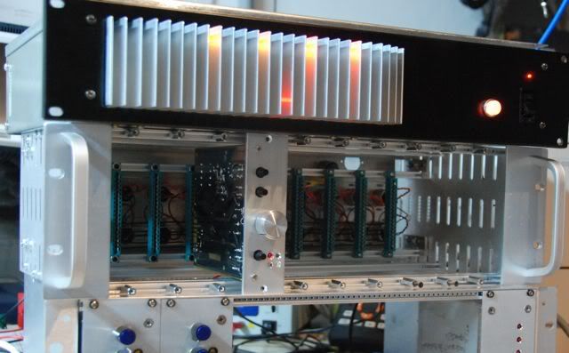
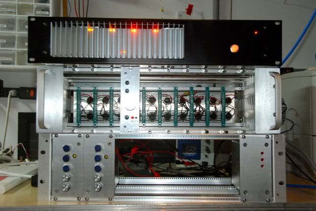
i put together a GDIY51x PSU using one of the Silent arts board and ClassicAPI toroid.  But no cases yet, so while I wait I ripped apart an old Altec Amplifier and an old Altec Preamp (that I had been harvesting Transformers from) and used the Heat sink from the Amp, and the case from the Preamp to make a nice little 2u 51x PSU.

Here are some pics

Front.jpg


I think the exposed heatsink looks nice, but it is practical too.  The heatsink protects the inside of the case from fingers getting in but leave a tremendous amount of opening into the case and because of gaps below and above the sink (I cut it much shorter than 2u) it creates a vent driven by convection.  Which I was pleased with because it is quiet.  

I made a mistake with the LED's (I am quite new to this electronic hobby) and so while it looks cool with the little LED's buried in the heatsink, the way I wired them they don't turn off when a fiuse blows.  I want a blown fuse to turn of one of the LED's to show me which one blew.  So I will have to update that, and that will run more wire around, which I would like to avoid.  It looks nice, one light for each voltage, the red one is for 48v.

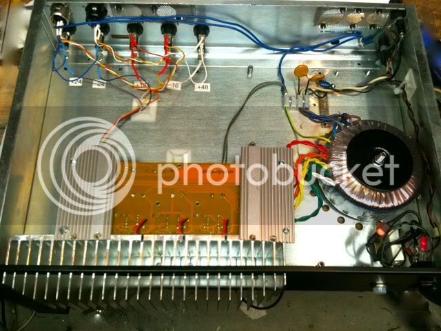
Guts.jpg


To get the heatsink arrangement to work, and be out front with the cool air (and good looks :) ) and to use the power entry that existed in the case, I had to turn the board upside down.   I wanted isolation... and well.... Distance is nature's Mu Metal.

By turning the case upside down I was able to keep the AC wiring pretty short, and keep it away from the DC.  And I tapped 4/40 holes in the back of the heatsink, sunk threaded rod into them and bolted the regulators right to the heatsink (with insulators of course).

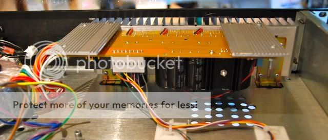
Vent.jpg


Here is a view where you can see the vent under the heatsink for the 48V, and also the space under the large heatsink. I hope that when the sink gets warm it will move the air out of the case, if I cap the inside top of the sink, I think it may be more effective, but at this point I am only powering 3 or 4 preamps with it (till I get my new toys), so it is pretty much overkill.  The little rack mount PSU you can see in the top picture actually powers my +24/-24/48 now with a wall wart.  


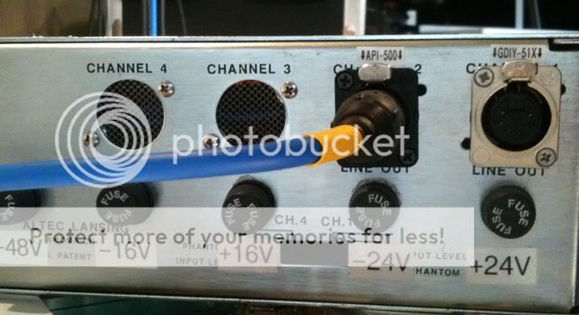
caseback.jpg


This is the case back, I wired it for API standard power as well as for GDIY 51x Power.  I used the XLR connectors and that West Marine cable that Chunger identified, which works nice.  Not super flexible, but it bends and coils, and is fine for me.  I put screens over the empty holes left over from the case's previous life.

I put the power on an oscilloscope and it is cleaner than what I was using, at least under some load.  Unloaded it has some sort of hunting oscillation maybe because the current through the adjust pin is too low to keep it solidly regulating?  But that is just an uneducated guess from a newbie.  Someone else might really know why it does this.  But when I plug the cable into a rack it settles down (even with just one preamp in the rack).
Front2.jpg


Another view showing the locations of the LED's

Bottom.jpg


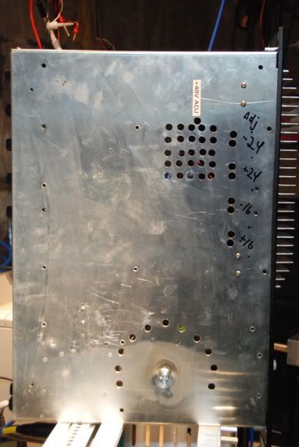
One downside is that upside down the voltage adjust screws were harder to access, but I don't need to touch them often.  There are two holes for each, one to look through, and one to put the screwdriver in.


WOW - very cool idea to mount the LEDs inside the heatsink :eek: 8)
you shouldn't change this beautiful housing (sorry Cemal & Jeff :D)

and WOW again: is this the first real 51X DIY case I see below the PSU? ;D
what is the module inside?
 
The module inside is a prototype, a simple OPAMP based preamp I put together, with harvested parts.  I am using it to experiment with a number of different concepts.

It is using a 1:10 step up Beyer transformer into an IC OpAmp (OPA2604) and running out through a 6 ounce output transformer I found in an old RTS preamp.  I had a few problems so that's why you might see some jumper cables in there.

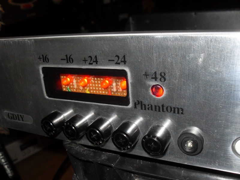
It has 4 lights.  Power, Phantom Power, and two peak detectors.

I built it with a little peak detector card that lights up the two different lights.  A little red light if I clip on output (which is pretty hard to do with a OPA2604 running on 24 volt rails :) ).  But the other light is a little green light, and it goes on when I hit the input voltage that is supposed to saturate the input transformer (in the case of the beyer, that is 300 MV at some frequencies).  So I can adjust the card to do these two peak measurements with the following purpose.

The Red peak light is obvious, I don't want to clip the preamp.

The Green peak light is a mission I have, which is to sort of understand what transformer saturation sounds like.  I plan on making a little card or plug to swap transformers so I can see if I use a little light transformer what saturation sounds like.  

(this has to do with a notion that if a particular transformer has a sound...then it must be distorting... and why would the creator only make expensive transformers sound good when they distort?  What does the sound of a cheap transformer saturating sound like?  So this preamp will help me listen to that... I plug in some little transformer from a old mixer, put enough signal through to blink the little green light, and see what I hear. But I don't know what I am talking about on this stuff, I can't measure it so I wanted to try to hear it. )

The other thing in that little module is that it uses a cheap pot to adjust a vactrol (LDR) to provide the op-amp feedback.  I did this to shorten the audio path, because I can put the Vactrol over by the opamp on the board like you would with a relay.  It seems to work, but I am wondering if I need to change the power for the vactrol to a current source to avoid some potential low frequency oscillation or variation related to power variations ( I haven't gotten to play with it enough yet, but I have not observed any variations, it is just that I saw a design for an LDR based volume control in the HiFi world and they used a current source and I wondered why.  Frankly... I only vaguely understand what a current source is!!!  But I am learning.

Anyway. the little preamp works, sounds clean enough, the vactrol control and peak detectors work (although I am using a quad fet op-amp on that peak detector that is running on 24 volts when it is spec'd for a maximum of 18... so I need to change the opamp, or do something to that part of the design in the next iteration.... But it works fine, and doesn't get hot.  I think it is a TL074.

I worry about effecting the input transformer with the peak detector.  The TL074 is JFET based so pretty high impedence but I don't know if it is loading or adding noise there ... or how to isolate that... I am still learning this stuff ... I started with electronics last november.

(and this has gotten way off topic for this forum, I would be happy to delete it or put it somewhere else if that is what one does (this is only my third post))
 
well.
nice psu case,
i never did upload a pic of mine
511psu.jpg


i still haven't used the 16v rails either.
what voltage should i be getting from the psu with no load?
what would be a safe test load and how would i rig it up?
 
Almost done with my dual supply case (eventually to be a triple supply)! So far all the voltages look great! Can't wait to put the finishing touches to it!
 

Attachments

  • 51xpsu.jpg
    51xpsu.jpg
    99.7 KB
kishibashi said:
Almost done with my dual supply case (eventually to be a triple supply)! So far all the voltages look great! Can't wait to put the finishing touches to it!

I am sure you realise that you'll require much larger heatsinks as the number of modules you are using increases.
 
Yes for now I'm just testing it on 10 VP26's and 8 550a's as well as 6 Empirical Labs Derressors. running nice and cool. I definately plan to add larger heatsinks... just looking for a good one that isn't too oversized. Also will be making the top and side panels "vented". I have to say its nice to not see the power rails sag like it does on my 10 rack API lunchbox under load. Its amazing how much money API charges for them too. I've had to send back 3 racks to them in the past.

When I hooked it up (luckily with no modules) I blew a cap in the PSU because the -16V and 16V rails in the API Lunckbox chassis were shorted together. So little space to work in a 7 pin xlr Neutrik panel connector back there with 22 gauge wire!  :eek: oops!
 
And thank you so much for making such a great build possible! My API complaints are finally over! Time to get my 1176 rev a problems sorted out..  :( BTW my power rail LED lights are going to be in the chassis on the 11th module spot... My patchbay is wired for 10 space API racks...
 
You are welcome.

kishibashi said:
I have to say its nice to not see the power rails sag like it does on my 10 rack API lunchbox under load. Its amazing how much money API charges for them too. I've had to send back 3 racks to them in the past.


I don't know how much you mean but it should not sag too much. I tested our psu in very harsh conditions and the sag was only 300mV.

Check this http://www.groupdiy.com/index.php?topic=33849.1120

Now, in terms of sag I smell a very common mistake in using 7 core wire. There are five rails riding on individual wires but all coming back on a single one as circuit ground. So the ground wire should be at least four times the thickness than the ones required for the rails. The 7 core we are supplying is 7x0.75mm which is the thickest that we could get.

By the way "kishibashi" means per person in Turkish. Sounds a bit whacky though like "kobayashi"  ;D
 
I tested our 10 space rack from API about a year and a half back. Under full load of 10 vintage 550a/b's my 16V rails were sagging by as much as 4V! My racks are all probably about 4 years old and don't know if they've fixed this problem yet...

I sourced my own 7 core wire and ordered a Belden 22aug 7 core wire! Its the reason why I ran out of space in the back of the chassis and the -16V solder point on the back plane pinched through to the 16V wire and shorted them together... haha

My name is Keita Ishibashi. Its japanese!
 
The sag on our psu was across both rails. The drop on individual rail was only 150mV. I was not aware of API sagging as much as that but it must have been a really bad design. I have no idea how a product like that would pass QC.

I should have anticipated your name as being Japanese. Well, there is always a link.

Regards.
 
****.

I mis soldered a gar2520 opamp and stuck it in a VP312 to test it.

I heard this nasty (very queit) 'meltdown' type sound. like a very high pitch sound going all the way down through the frequency range. I panicked and switched off straight away.

I tried to power the existing pres in the rack back up, with the offending pre taken out. ****. Nothing.

So, i've tested the pres themselves in my Lunchbox. All work, no problems there.

It can only be the PSU. I am worried.

Help!

To describe the sound, it was like when Obi Wan turns off the tractor beam in Star Wars, only real quiet.

Is this the sound of something burning out? The mains light (on the switch) is on, when I switch it on, so there is clearly power getting into the PSU PCB (well, at least I think), but not to the rack it seems.

Any thoughts on this greatly appreciated. Has anyone had any experience of a PSU blowing due to a faulty opamp? It seems odd to me.

To my memory, the only fuse is the mains fuse. THe switch wouldn't be glowing if that was the case. I'm worried guys

Matt

 
Man, if you worry over a lousy psu just don't get married. You think that's a meltdown type sound?

I understand you did not have fuses on the output. The worst can happen is the regulators will go bust.

Leave the psu unconnected to the rack.

Power it up but watch for any abnormal occurance. If the transformer is not buzzing and no smoke coming out first do a visual check if there are any burnt components, then start to read the voltages.

Read transfromer output (AC) on the terminal block.

Read the unregulated DC between the input pins on the LM350s.

Check the protection diodes. Just de-solder one end and measure.

If  all o.k.

Replace the regulators.

 
Hi,
you should certainly give more details about your build and testing of the "faulty" power supply for anybody to be able to help. Seems like power's going in but did you test the output rails, are your output fuses ok, take a picture of the power supply etc... Cheers.
 
sahib said:
Man, if you worry over a lousy psu just don't get married. You think that's a meltdown type sound?

Hahahaha, yeah, you should see what she's like when i've been in the studio all weekend. she burns my dinner deliberately!

Guys, i've pulled the beast out, along with the rack and will be setting to testing stuff around the 4pm mark. will report back

M
 
Cemal

I checked all the outputs from the PCB. I think i've narrowed this down to Phantom power.

I'm getting positive readings on teh +16, -16, +24 and -24 rails with it hooked up to the rack, but i'm getting squat on the 48v.

Thing is, I checked the fuseholder (after the pcb/I.e. below LED which i still haven't got round to hookin up).

The 48v fuse appears not to have blown - I am going to change it anyways

M

 
No SMOKE!!!.... but no +24 or +16v either voltage either.

OK.... so being a complete noob I think I may have attempted to power the PSU incorrectly wired to the IEC. I got that figured out and all is well on that end however, could this or would this somehow only take out the +16 and +24 because the other rails are testing just fine.

And it's that way on 2 PSU's that I am running in parallel off of the leads from the toroid.

On one of the PSU I went ahead and used a spare LM317 I had laying around on the +16v and no dice.

I am puzzled about where to look next.

Input much appreciated!
 

Latest posts

Back
Top