official GDIY51PSU Help & Support Thread

GroupDIY Audio Forum

Help Support GroupDIY Audio Forum:

This site may earn a commission from merchant affiliate links, including eBay, Amazon, and others.
kepeb said:
hey,
glad to help out but i'm not following, sorry :(

what is your torroid first off?
:)

Thanks kepeb -- my transformer is an avellindburg Y236402. http://www.avellindberg.com/transformers/y23_range_specs.htm.  Basic 2X18v toroid. 

So, according to the label on the transformer , I have 4 wires coming off the secondaries (blk=0v and red=18v, ora=0v and yel=18v).  There are 4 terminals (of interest) on the 51x PSU board, but each pair has only one label - 16v.  So which wire goes where? 


Hey guys, project completed and already in use with a pair of VP26.

I wanted to post a picture of my PSU (it is indeed my first build and therefore doesn't look very good) and talk about the regulators heatsinks. As I was browsing the forum I couldn't help but think that those huge heatsinks you guys have been using in your builds were a little over the top (sizewise). I ended up buying really small ones online, but now that they're installed I find myself thinking I may have seen small on this one. What do you think? I'm sure its totally adequate to run a single pair of Jeff's fine mic pres, but how will my PSU react with a full rack?

By the way, Many thanks to Volker and Jeff for their fast replies to all of my questions. And thanks to everyone involved in making the GDIY511, awesome project.

Alexis.
 

Attachments

  • PSU1.jpg
    PSU1.jpg
    180.7 KB · Views: 119
Wow, thanks Brolik. This is exactly what I was looking for. In the process of assembling mine now, and this is nice to reference.
 
George Adamski said:
... As I was browsing the forum I couldn't help but think that those huge heatsinks you guys have been using in your builds were a little over the top (sizewise). I ended up buying really small ones online, but now that they're installed I find myself thinking I may have seen small on this one. What do you think? I'm sure its totally adequate to run a single pair of Jeff's fine mic pres, but how will my PSU react with a full rack?
Hi Alexis, it depends very much on the modules in a full rack.
the oversized heatsinks are for the real maximum, however - there is no module drawing the max. current on all 4 (5) rails.
 
I'm about ready to do the chassis wiring. Is there any wiring diagrams for the point to point stuff? The picture above is great, but I can't make out all the detail. I'm using the same transformer, so I can get that. But the wiring between the power switch, fuse holders, LEDs, etc is what I'll need to figure out.

1. Do I take the outputs from the ps board (+16/-16, etc) and wire to the fuses, then from the fuses back to the 7 pin plug going to the rack?

2. How do I hook up the LEDs on the front panel? I found an earlier explanation. Are the necessary resistors not included in the kits? On the ps motherboard LEDs, do you have to flip the anode/cathode for the negative voltages? (ie -24 would have cathode to the square + pad)

3. How do I wire up the main power? This is Jeff's transformer.
This is my main issue. If I can figure this out, then I can at least check for some voltages.

ps1.jpg
 
I'm looking for cable from the psu to the rack and
because it's hard finding 6/7 conductor  20 gauge
I'm considering smaller gauage & doubling up wire

24 & 24 will not give me 12 ? can any of the supplies [ 48 ? ]
get away with less than 20 gauge ?

OR what / where is anyone getting cable from ?

tia , regards Greg  
 
Rob,

Here is some text that came from a couple of emails with two different folks. I have edited it to make the most sense (hopefully!).

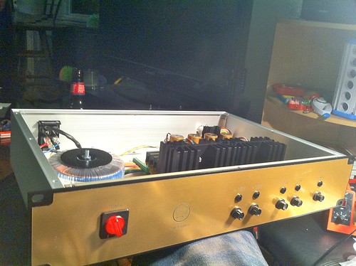
I am pretty certain 'Chung will have pictures that will make use want to eat the inside of his PSU case for dinner!  :D

These are verbal descriptions but do make sense if you read thru them carefully and visualize or even make a sketch.

All of these references are from a viewpoint if you are inside the case looking at the inside of case side of each part.
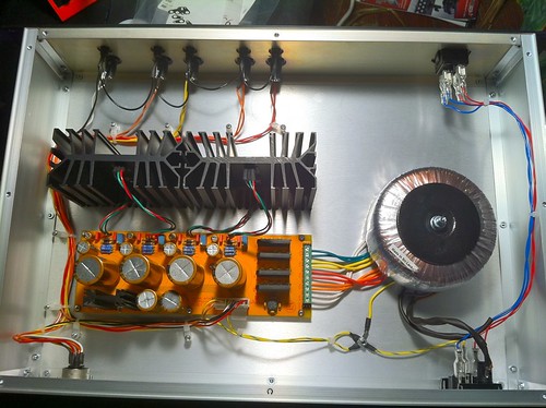
IEC
-Top Lug of IEC --> Chassis star ground stud
-Right Lug of IEC --> Fuse Holder Side Lug
-Left Lug of IEC --> Top Right Lug on front panel main switch

Fuse Holder
-Fuse Holder Center Lug - Top Left Lug on front panel main

Voltage Selector
-Lower left lug --> Toroid Brown & --> Bottom Left Lug on front panel main switch
-Upper left lug --> Toroid Gray
-Upper right lug --> Toroid Violet
-Lower right lug --> Toroid Blue & --> Bottom Right Lug on front panel main switch

The pdf on the toroid page of my site will help you confirm all of the connections for AC between the toroid and the PCB.

Star Ground Stud Connections
-Connection to upper lug on IEC(already mentioned above)
-Green/Yellow Screen from toroid
-CHASSIS plated thru holes on PCB beside the AC inlet header
-GND plated thru holes on PCB on the other side of the AC inlet header

I should also mention that these notes are specifically for the lead colors on the toroids that come from me only. I am pretty sure they will be different if your toroid came from Cemal or Volker.

Hope that helps!

Cheers, Jeff
 
Thanks Jeff!

That was all I needed. I hooked up the transformer and mains, turned it on, used my meter and adjusted screws and got exact voltages from the lug terminal that powers the rack.

1. Do I set these voltages with no load?

2. Your notes said to connect both ps circuit board through holes "Chassis" and "Ground" to star ground. If I do this, then is there any difference between the two? Just curious as the rack backplate has "Pin 1 to chassis" and "Pin 1 to ground". Would these make any difference then?

3. I installed the LEDs on the ps circuit board, but none of them light. (I have yet to hook up the front panel ones, but since I'm getting voltage those should work fine). Are the ones I wired onto the circuit board (assuming that was what those extra holes were next to the trim adjusters) supposed to light up? I wired the anode to the square through hole pad on each.
 
Rob,

1. You can set the voltage with no load. I usually go about .75 to 1V high as there will be a drop across the 1N4004 protection diodes on the individual module's cards.

2. Yes, connect both of the pads to the star ground. The only place the Chassis and Ground planes from the rack ever connect, should be at this star ground stud in the PSU case. Unless I am forgetting something, you would have to jumper a single pin 1 to both Gnd and Chassis to create a loop and defeat your star ground. Of course this could be done with a mistake on a module's PCB too so I suppose you should always be familiar with what you are putting in your rack. FWIW, I have started incorporating a 10R between Chassis and Ground on my module PCB's just to be sure they are locally isolated. This will also give phantom a return path in case the Chassis has been floated somewhere thru the circuit.

3. Turn them around and they will light.  ;)

Cheers, Jeff
 
okgb said:
I'm looking for cable from the psu to the rack and
because it's hard finding 6/7 conductor  20 gauge
I'm considering smaller gauage & doubling up wire

24 & 24 will not give me 12 ? can any of the supplies [ 48 ? ]
get away with less than 20 gauge ?

OR what / where is anyone getting cable from ?

tia , regards Greg  

Rule of thumb:
To double the current capacity of a wire, go down 3 gauges.
2 24 gauge wires in parallel are about the same as 1 21 gauge wire.
Hope this helps!
Best,
Bruno2000
 
The red LEDs on the power supply mother board didn't work, so I was told to flip them around. Well, getting them out destroyed one of them so I need a new. Is there any specific type I need?
I have one here. If I check resistance its at 1.47 instead of 1.58 of the ones I got in my kit. Is it ok to use that one, perhaps on the 48 volt indicator?


Update : I soldering in the LED I had and it works. Not quite as bright, but it works. Earlier in the thread there was talk of dual colored LEDs. Are the circuit board LEDs that come with the current kit dual color?
 
I've got the power supply working, the circuit board LED lights go on, and I can measure and set voltages. Now on to the wiring of the fuses, front panel LEDs, and Neutric connector.

ps2.jpg

ps3.jpg
 
Its done! All voltages read correctly. Tomorrow I'll load it up with some modules and test it out.

ps4.jpg

ps5.jpg
 

Latest posts

Back
Top