ruffrecords
Well-known member
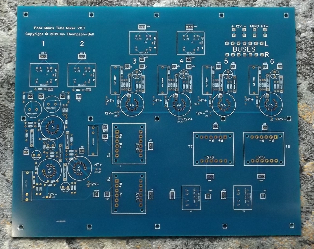
Tubetec said:I just saw the PNG image of your layout ,
You have the gain blocks down to a very tidy footprint , that should pay dividends
The idea about the heaters also makes good sense , it allows the heaters to be run in the traditional manner ,twisted pair ,looped up and away from sensitive circuitry and on to the next valve . It also means less chance of any leakages or coupling between heaters and other electrodes .
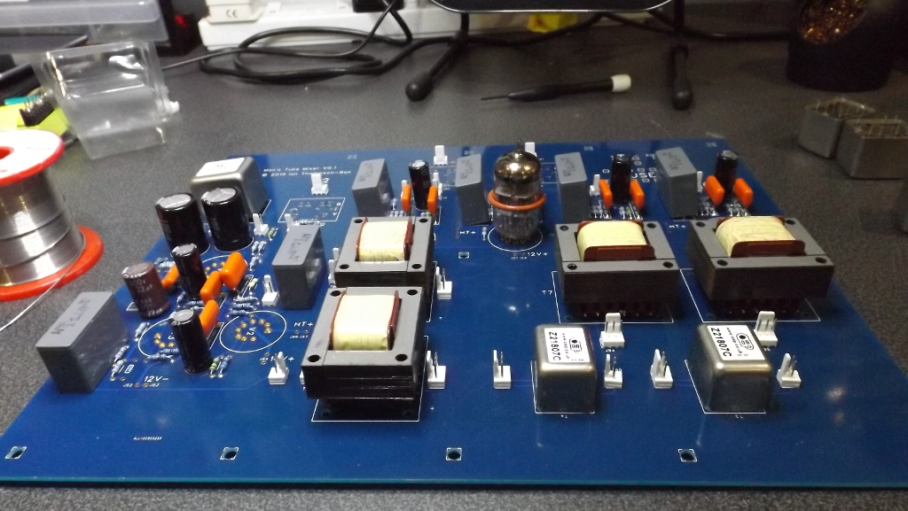
One thing in the PNG above is some of the electrolytics are very close to valves , of course on one hand physically adjacent to the components or electrodes your bypassing is good news , life expectancy of electrolytics in very close proximity to valves might be somewhat limited though . One possible way around this is to mount the electrolytics on the backside of the board ,there no further away than right way up but more or less completely shielded from the direct heat of the valve , that could increase the lifespan by years.
I take your point about electrolytic capacitors. There are two of them quite close to V1. However V1 is a 12AX7 running at about 0.5mA plate current and 90V plate voltage so its dissipation is quite small. The only real heat is from the heaters which is only 3.6W. All the other tubes are 6922s running at about 6mA and 125V plate and I keep electrolytics well away from them
Cheers
Ian


![Soldering Iron Kit, 120W LED Digital Advanced Solder Iron Soldering Gun kit, 110V Welding Tools, Smart Temperature Control [356℉-932℉], Extra 5pcs Tips, Auto Sleep, Temp Calibration, Orange](https://m.media-amazon.com/images/I/51sFKu9SdeL._SL500_.jpg)