Poor Man's Tube Mixer

GroupDIY Audio Forum

Help Support GroupDIY Audio Forum:

This site may earn a commission from merchant affiliate links, including eBay, Amazon, and others.
It's good to know that even really seasoned tube  'builders'  make little slips occasionally, of course then quickly fixing it up!

Makes me feel a bit better in light of some of my own mis-calcs  :)

Sorry - just a bit of 'grey humour' !
 
alexc said:
It's good to know that even really seasoned tube  'builders'  make little slips occasionally, of course then quickly fixing it up!

Makes me feel a bit better in light of some of my own mis-calcs  :)

Sorry - just a bit of 'grey humour' !

As it says in my sig, the only people not making mistakes are the people doing nothing.

Cheers

Ian
 
I purchased five prototype PCBs. One I am building. Three of the rest have already been shipped to eager experimenters.

There is one left. Cost is £37 including tracked shipping etc.

Cheers

Ian
 
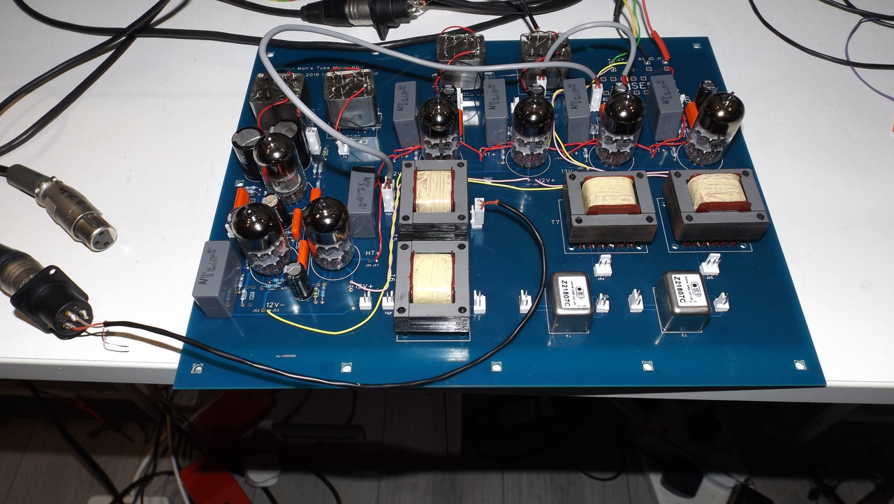
I have now glued all four  mic input transformers upside down on the PCB and hand wired them in (due to the error I made in the transformer footprint). This evening I connected each in turn via one of the mic pre amps and verified they are wired/work correctly. Laos checked overall gain via mu follower stages is 42dB (with input and output transformers). Rough noise measurement indicates EIN is in the -122dBu region.

basictests.jpg


Cheers

ian
 
ruffrecords said:

Hello Mr. Thompson-Bell & GDIY

I am again in awe of your efforts to create accessible audio systems. This is exactly the build we envision (without actually knowing we were envisioning it!). Modular in concept and functionality....and all Tube, solid.

I cannot comment on sound until i implement in on a Dolby Atmos film mix.

The Metacase you selected brought this mastering console to mind by James Fei. I really like this design which you have likely seen.
https://www.jamesfei.com/recording.html

Tactual, easily adaptable to a small producers suites, voice over/pod cast professional or large live tracking scenarios. I cannot envision the complete unit "sitting on the sidelines".
My wife wants our son to build this now, is this possible?
To understand something my wife HATES tube amps. She HATES my tube amp collection. But she is a HUGE fan of your approach to product based education, or "apprenticeship" styled training.

I highlight Voice Overs and Podcast as this is a HUGE market that is untapped in terms of niche focus directed at their specific requirements. Along with a Microphone Parts DIY Tube Mic Kit, this is as affordable way to learn to master ones goals.
 
The poor man's tube mixer (PMTM) is a work in progress, in fact it is in the very early stages of development. So far, the PCB you see is all there is. This is still being commissioned and tested and it contains known errors. Once that board design is complete there is still have to design the front panel PCBs on which the various controls are fitted. There will be several of these to allow builders some flexibility in configuring their mixer. The there is the rear panel to do. Then the whole thing needs to be built and of course there is a power supply to design and build. I expect it will be several months before I am anywhere near to releasing the completed design
Talking of front panel layouts, the one you linked to is very similar to the initial one I created. I did this only to confirm that the necessary controls for the standard version would fit on the Metcase front panel. It is by no means definitive but it has a remarkable resemblance to the one you linked to (pdf attached).

Cheers

Ian
 

Attachments

  • FrontPanelBasic.pdf
    7.9 KB
Any chance of future boards could accept a choice of input transformers like the classic solo? The Cinemags worked great for me on the Solos, good price too here in the US.
 
lestatdog said:
Any chance of future boards could accept a choice of input transformers like the classic solo? The Cinemags worked great for me on the Solos, good price too here in the US.

Way back in the early days of the EZTubeMixer project I created a single footprint that would allow Jensen, Cinemag and Sowter mic/line inout transformers to be used. However, they are all really top of the range types and hence quite expensive. For the poor man's tube mixer I wanted to substitute a much cheaper OEP alternative. Unfortunately it is not possible to combine its footprint with the other three. So, as far as the PCB layout is concerned it becomes an either/or situation and there is not room enough to include both footprints side by side. Bottom line is I would have to make a special version of the  board with the OEP footprint replace by the EZTube one. I am happy to do this as long as there is enough demand for the special board - basically 5 boards.

Cheers

Ian
 
I have been working on the front panel and its associated PCB. Attached is a copy of the current front panel layout. This has two EZTubeMixer mic pres with stepped gain controls, the usual 48V/pad/mic/line/phase switches plus a pan pot and a rotary fader. The blue shading indicates the size of the knobs, 15mm for the pan and 30mm for the fader.  The stems have their own fader and there is a master fader of course. The meter cut outs are designed for Sifam R22A style VU meters.

The PCB follows the Mark 3 style by mounting directly to the front panel via the toggles and pots. Connections to and from the main board are via Molex connectors. There is still a bit of tweaking to do but I want to order the front panel from Scheaffer before Brexit!

Cheers

Ian
 

Attachments

  • FrontPanelBasic.pdf
    10.8 KB
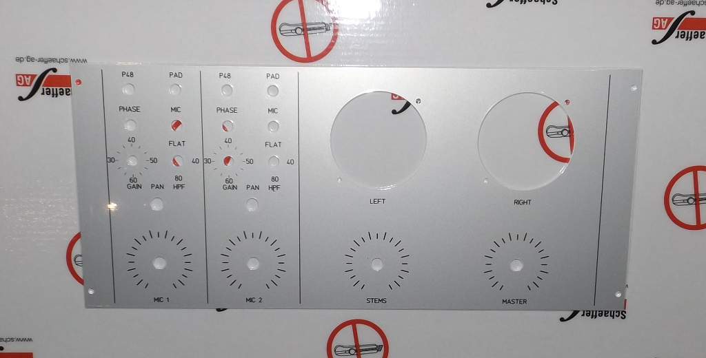
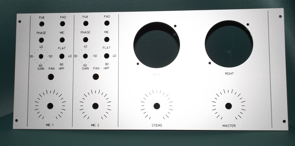
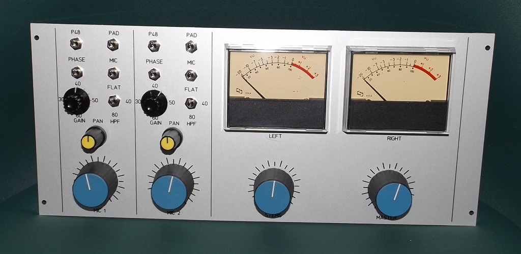
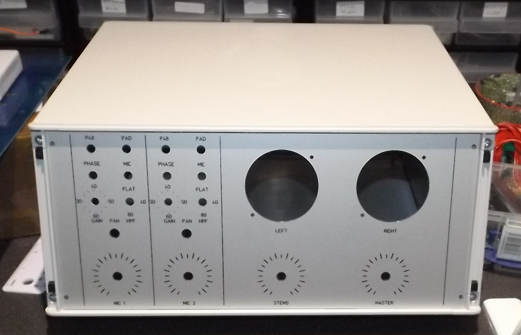
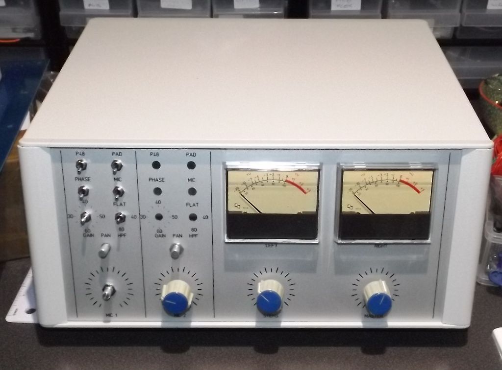
The front panel itself and the front panel PCbs for the two mic pres arrived recently. I have partially built the front panel PCB to the point where I can check it actually fits the front panel;

Front panel as received from Schaeffer:

Front-Panel-As-Delivered.jpg


and after unpacking:

Front-Paenel-Unwrapped.jpg


Then offered up to enclosure to make sure it fits:

Bare-Front-Panel-Fitted.jpg


and lastly with partially populated front panel PCB fitted, a couple of SIFAM meters and some wrong size knobs I had lying around:

Part-Built-Unit.jpg


More when I finish and test the front panel PCBs.

Cheers

Ian
 
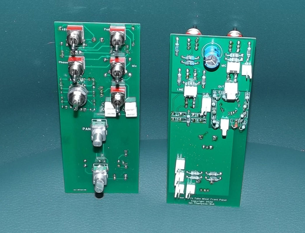
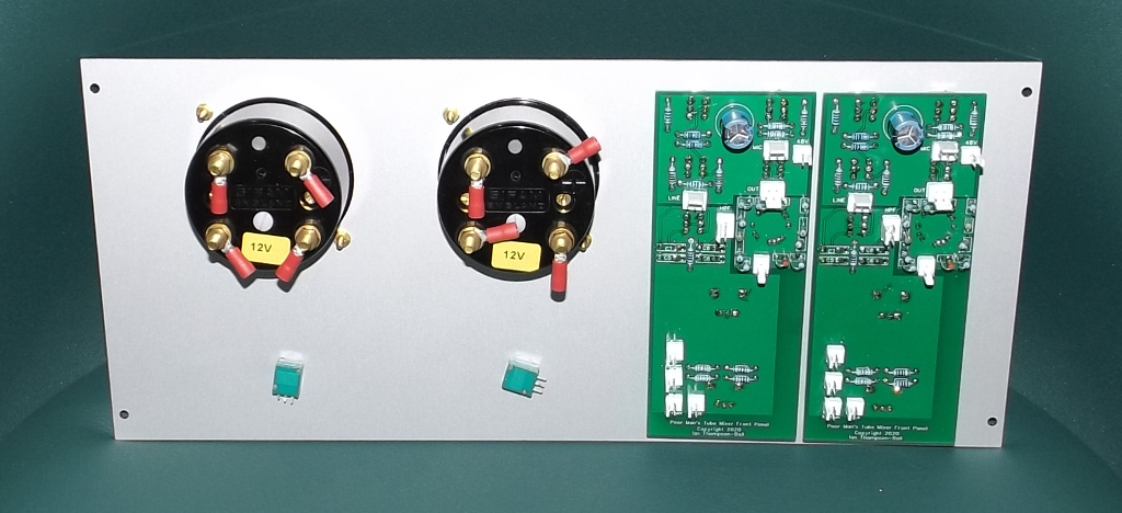
The remaining parts for the front panel PCBs have arrived.

Completed PCBs:

frontandback2.jpg


Fitted to the front panel with knobs fitted:

Fully-Built-Unit-With-Knobs.jpg


and the back side of the same:

Fully-Built-Unit-Rear.jpg


Waiting now for fixings to mount main board in enclosure. Then I can mate both boards and test actual channel functions.

Cheers

Ian
 
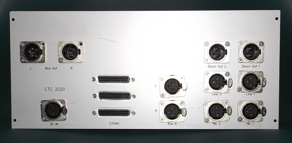
Rear panel has now arrived but unfortunately I made a few mistakes in its design so it has taken a while to find work arounds. I got the size of the XLR holes too small so that meant a lot of filing. I thought I got it right by using a male XLR as a test connector but when I assembled it I found the female XLRs need a slightly larger hole so the cable release button will work. Also the bottom of the XLRs obscures the legend on the panel so for the final version they will need to be moved .So I took it all apart and did a load more filing. I then realised that by rotating the XLRs through 90 degrees I could see the legend again. So I then had to drill another set of fixing holes (fortunately the XLR covers up the old ones) and mount all the XLRs at 90 degrees. This is the result:

Rear-Panel-Populated.jpg


A bit scrappy but it works.

Cheers

Ian
 
That all sounds like a right royal PITA, just what you don't want to have to deal with.

I guess it is supposed to teach you patience, equanimity, or something. It must get to a point where you don't need lessons anymore, right?
 
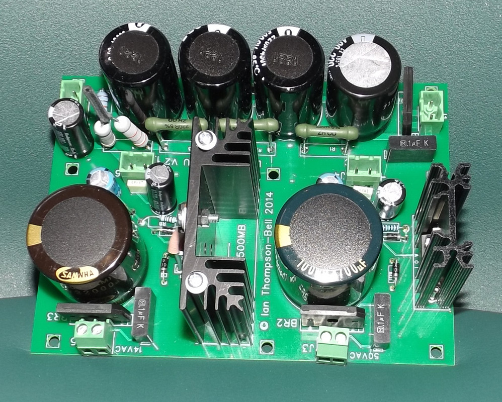
I have now finished building the separate power supply board, This will be housed in an external enclosure to keep hum to a minimum. The board is the old lunch box power supply from 2014. Still a very good basic  tube power supply which, with suitable mains transformers, can provide 300V at up to 100mA, 12V at up to 3A and 48V at up to 100mA.

Power-Supply-PCBComplete.jpg


Cheers

ian
 

Latest posts

Back
Top