Poor Man's Tube Mixer

GroupDIY Audio Forum

Help Support GroupDIY Audio Forum:

This site may earn a commission from merchant affiliate links, including eBay, Amazon, and others.
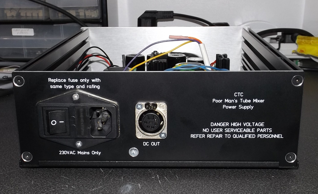
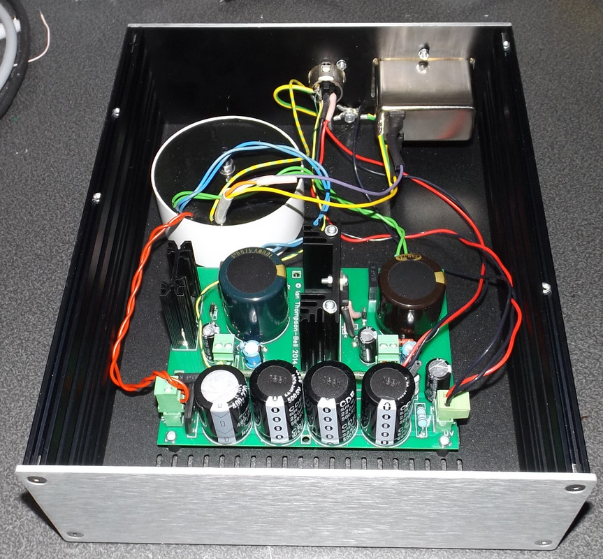
As promised a pic of the completed power supply:

PSUcomplete.jpg


and its rear panel courtesy of Schaeffer:

PSUrearcomplete.jpg


Cheers

Ian
 
BluegrassDan said:
Did you send the panel to Schaeffer, or did they just make a new one to specs?
They made one from scratch. Modushop provide dxf files of their cases so it is easy to draw up a panel.

Cheers

Ian
 
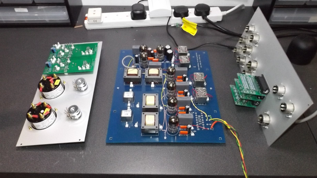
I now have the three main components; front panel, main board and rear panel, set up on the bench ready to start wiring it all together.

Three-Main-Parts.jpg


Cheers

Ian
 
For some time I have not been enamoured of the off the shelf enclosure I chose for this project. It is a nice shape and is reasonably priced but..... the large main board on the floor is wired to the rear panel and also to the front panel. The more I get through wiring these three together the greater the maze of wires. I really am not looking forward to trying the wiggle these three big components into the enclosure whilst ensuring none of the cables gets too close to a tube. And I really don't fancy taking it apart again if something goes wrong.

The 'Neat Enclosure' thread I started back in mid February suggests I was not really happy with the current enclosure more than two months ago. Fortunately, KidS|quid in that thread has come up with some good ideas which make the whole thing look a lot more like a small mixer and could simplify assembly considerably. So as of now I am putting the whole project on hold whilst I resolve this issue.

I will keep you all posted.

Cheers

ian
 
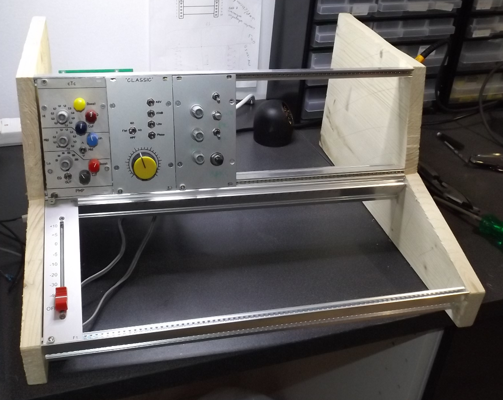
To whet your appetite, here is a pic of a lash up I put together the other weekend just to get a feel for what it will look like:

PMTMlashup.png


Cheers

Ian
 
Beautiful Ian, I hope I one day can build a small tube mixer for my studio.

Quick question (might be answered somewhere else, sorry if so): what ht voltage does the TLA expect? I am playing with the idea of adding one of these boards on the input side of the DAOC I'm building to use it for input gain (so I can use trimmers in place of the pot meters in the compressor circuit to accurately match gain between channels) and was wondering if I could use the transformer I'm using (250ac secondaries + 9v for the heaters)


Se orry if I'm off topic, and looking forward to the continuation of the thread!
 
fragletrollet said:
Beautiful Ian, I hope I one day can build a small tube mixer for my studio.

Quick question (might be answered somewhere else, sorry if so): what ht voltage does the TLA expect? I am playing with the idea of adding one of these boards on the input side of the DAOC I'm building to use it for input gain (so I can use trimmers in place of the pot meters in the compressor circuit to accurately match gain between channels) and was wondering if I could use the transformer I'm using (250ac secondaries + 9v for the heaters)

The TLA will work on any HT voltage from 250V to over 300V. It requires 12V heaters, preferably DC.

Cheers

Ian
 
Hey Ian, thanks for your reply.

I am building a D-AOC as my first tube project. I've been at it for a while and the compressor is basically ready for first fire-up very soon.

Many people over in the D-AOC thread is noting that that the compressor needs to be driven at quite high levels to compress, altough using higher ratio input transformers and back to back vactrols lower the threshold. I am using lundahl 1540's on the input in a 1:1 ratio so I think I might benefit from some gain on the inputs, and rather use the input controls on the d-aoc for calibration of the stereo signals. So I've been tinkering with the idea of adding a TLA to the input of the compressor and am curious as to how feasable the idea is.

I don't know if you're familiar with the D-AOC design, here's the schems:

http://www.silentarts.de/DIY/D-AOC/D-AOC_Schematic.pdf

and board overlay:

http://www.silentarts.de/DIY//D-AOC/D-AOC_PCB-Overlay.pdf

My power transformer has 250V (0.1A) + 9V (2.5A) + 24V (0.5A) secondaries. I'm not sure of the current draw of the circuit, and am wondering if the transformer has enough B+ and Heater current to drive the additional TLA with the D-AOC psu (as you state in your documents this should be no more than another 15mA B+ or thereabouts configured as a line driver?). The B+ PSU form the D-AOC is the same as the GYRAF HT supply, don't know if you're familiar.

I see the TLA wants an elevated heater and minimum 250V B+. Here's some voltages from a working D-AOC:

https://groupdiy.com/index.php?topic=26585.msg330048#msg330048

Could I take the B+ from say before R128 and use it for the TLA? I presume that this is a little over 250V. For the elevated heaters, could I make a circuit as in your HT250 schematic, with a voltage divider from the B+ (again from the same place, just before r128) using 2x33k 2w(in paralell? r4 in HT250 schems) to a 22k 2W (r5 in HT250) with a 100uf cap (C5 in HT250) from the elevated heater to ground. I see this voltage divider also is used as a bleed resistor for the B+ when the unit is turned off, wondering if this will eat too much current for the power transformer, if there are other resistors in the D-AOC that acts as bleed resistors?

Could I use the lundahl 1540's directly to the TLA, and go unbalanced from the TLA to the D-AOC?


Lots of questions, I hope I don't derail the thread but I've beenr reading up on all your wonderful documentation and got curious.

Thanks for any input and all the best,
Magnus
 
Looking at the D-AOC schematic you posted I see that immediately after the Vactrol gain cell there is a 20dB amplifier. This then feeds the side chain triode which probably has another 20dB of gain. This should be plenty of gain to ensure the gain cell  compresses.  The VTL5C4 only needs 1mA of current to drop its resistance to 1K2 which should give plenty of gain reduction with R102 at 8K2.

One reason it may not be working properly is that the Vactrol LED really needs another LED across it wired in opposite polarity. A red LED will do fine. Otherwise the circuit acts as a charge pump. I believe this is a well known flaw in this design.

Cheers

Ian

Adding a TLA at the input would increase the gain and lower the threshold but also raise the noise. I
 
The stock build uses vtl5c4/2 plus a resistor as you say, the way I'm setting it up is with two vactrols pr channels, one reversed so will act as the led with opposite polarity (Kubi mod). Some builders say they needed the input and makeup-gain in order to trim the compressor channels to each other, and that 1:1 ratio on the transformer is too low for the gain available on the input of the compressor to hit the vactrols with a wide variety of input levels.
I'm sure I'll have a better picture of it all when it's built up  8)

Best,
 
I have continued to work on ways to reduce cost. it occurred that in the present 7 tube design we actually have two pairs of buses. One pair for the DB25 balanced line ins and another pair for the master bus. The I thought, why not just use the DB25 balanced bus for everything. Unbalanced mic pre output can still be fed to this bus as an impedance balanced source, adding optional bus expansion inputs then becomes trivial and optional balanced line inputs with individual level controls and NYD style LCR pan switches also become possible.

Downsides are first we lose the ability to smooth pan the mic pres but as they will mostly be used for tracking an LCR pan should be fine. Lastly there no opportunity to place the bus master control before the bus amp so it will have to be on the output. Again not really a compromise in most cases.

Bottom line is we can now construct a minimalist mixer with just 4 tubes ( two for the mic pres and two for the buses). Slightly more flexibility comes if we use 6 tubes ( two TLAs instead of two Classic modules).

Schematic attached for 6 tube version.

Cheers

Ian
 

Attachments

  • PMTM-Balanced-Passive-Bus-Version-1.pdf
    90 KB
scott2000 said:
Thanks Ian...Is the drawing correct? I'm having a difficult time following it. Just want to make sure...

Well it is more a block diagram than a full blown schematic. Please feel free to ask if anything is not clear.

Cheers

Ian
 
ruffrecords said:
I now have the three main components; front panel, main board and rear panel, set up on the bench ready to start wiring it all together.

Three-Main-Parts.jpg


Cheers

Ian

Very interesting project.
Following with attention.
Have you got any board available (maybe spare prototypes)?

To keep costs down what are output transformers options?
I see in other of your projects you suggested Edcor or Carnhill.
But I can't recognise this particular output transformers in photo.
I checked all the thread but maybe I missed something.
I found OEP a very good option as input transformers.
Perform well together with other expensive options.

Thanks
Alex
 
Aleguitarpro said:
Very interesting project.
Following with attention.
Have you got any board available (maybe spare prototypes)?
I made all the spare protoype main PCBs available here at cost. I have one left if you are interested
To keep costs down what are output transformers options?
I see in other of your projects you suggested Edcor or Carnhill.
But I can't recognise this particular output transformers in photo.
I checked all the thread but maybe I missed something.
I found OEP a very good option as input transformers.
Perform well together with other expensive options.
There are lots of transformer options. I suspect the transformers will be the parts most often changed by constructors.

On the input side the design uses OEP transformers for the mic input and bus expansion inputs to keep costs down.

On the output side you can use no transformer at all and instead use an impedance balanced output. Or you can use the  normal Carnhill (VTB2291) and Edcor  (XSM2K4/600) types that go with my designs. The transformer you do not recognise is one that was designed here by CJ and which I have manufactured by a local company. Its costs lies somewhere between that of the Edcor and the Carnhill types. It has the advantage of being PCB mounted. I am happy to pass some of these on at cost if people want them.

Lastly, you should know that I am not proceeding any further with those particular PCB designs. As I have said in an earlier post, the sheer volume of wiring between the main board and the two panels makes them impractical and very difficult to service. This has caused me to re-evaluate the method of interconnect and revert to the motherboard method I use in the EZTubeMixer project.  I have also been disussing the project with several potential customers whose input has been invaluable. This has cause me to revisit the overall design several times in an attempt to reduce cost yet retain flexibility. The schematic posted above is the latest attempt.

I am currently working on a new enclosure design that is compatible with the EZTubeMixer motherboards which actually looks like a mixer (you can fit real faders to it if you wish) and I hope the have something to show in a few weeks time.

Cheers

Ian

Cheers

Ian
 
Back
Top