PRR Vari-mu

GroupDIY Audio Forum

Help Support GroupDIY Audio Forum:

This site may earn a commission from merchant affiliate links, including eBay, Amazon, and others.
Duka,

51k pot is close enough. Yes, R39 is a dual pot when running stereo. If you look at the pictures of my lame old proto on Kev's page you can see it up in the corner. As far as R32, just set it up like PRR suggests. Run some clicky stuff with lots of bottom - kick drum in other words - and adjust for minimal "thump". It's really pretty forgiving as far as that goes. When it comes to the scale of the meter I'm pretty sure it's 1mv per db so there's really no "scaling" involved.

cheers,
kent
 
I found a really interesting tidbit of information the other day. I tried a few different opamps for the SIDECHAIN opamp, yep the sidechain. I found that they sound very different. Most would disagree but I was comparing the mc33079, tl084 and opa404. the tl084 had the most low end and least high end. the highs seemed to be controlled by the relatively slow slew. the mc33079 sounded different but still bassy. the opa part had the most detail by far but the bass was overly controlled, very bright sounding output.
 
[quote author="Svart"] the tl084 had the most low end and least high end. the highs seemed to be controlled by the relatively slow slew. the mc33079 sounded different but still bassy. the opa part had the most detail by far but the bass was overly controlled, very bright sounding output.[/quote]

which opamp did you end up leaving in the circuit?
 
Hi,

once again a question concerning the PSU:
At 230V (I'm in Europe), using Kents PCBs, could I get away with using one 230V>12V transformer and then use only one winding of another transformer (12V>115V) for the high voltage?

Thanks alot!

Kind regards,
Gregor
 
living sounds,

I've done what you suggest, it works (the same principle is often used in the Gyraf DIY stuff)
It's not ideal because of the loss caused by the two TX wired back to back.
but at least for me it worked good :razz:
 
flaheu,

thank you very much! Sounds good. What I don't understand is how you can actually use the two windings of a single transformer for different tasks, as suggested for the original project - wouldn't they influence each other? Using two transformers looks like the cleaner way to me... But then, I don't even understand why one would transform down and up like it's done in the Gyraf Pultec (see my other post)...


Kind regards,
Gregor
 
[quote author="living sounds"]What I don't understand is how you can actually use the two windings of a single transformer for different tasks, as suggested for the original project - wouldn't they influence each other? Using two transformers looks like the cleaner way to me...[/quote]

Transformers with dual secondaries are the norm in tube amplifiers. Two seperate windings doing two different transformations do not get in the way of one another.

[quote author="living sounds"]But then, I don't even understand why one would transform down and up like it's done in the Gyraf Pultec (see my other post)...[/quote]

It can be tricky to find a dual secondary transformer with the right voltages for a reasonable price. Gyraf used these inexpensive and compact torroids (and being torroidal means less electromagnetic interference flying around in your box), and found a way to derive both voltages needed at a lower cost and space usage than with a dual secondary type.

Using two transformers both attached to mains makes power switching more complicated, and you would need another fuse.
 
Skipwave,

thanks! I think I still don't understand the circuit. Why do you need a second transformer for the Pultec in the first place? One transformer I understand, since that's the one to get the heater voltage. But why a second one? Couldn't one just use the 220V from the wall outlet, instead of transforming it first down to 12V and then up to 220V again?
It's probably a really stupid noob question, but I've searched this forum and the net for hours to find out more and couldn't come up with an answer.

Regards,
Gregor
 
Why would there be any advantage in terms of safety? You could put a fuse in there without using a second transformer. As for world wide - no, it definitely won't work at - say 110V - without applying the changes Jakob suggests in his schematics.
 
[quote author="living sounds"]But why a second one? Couldn't one just use the 220V from the wall outlet, instead of transforming it first down to 12V and then up to 220V again? [/quote]

Oh, goodness, don't do that. I don't explain this very well, but I'll try.

A power transformer, even a 1:1 turns ratio isolation transformer provides a measure of safety that is crucial. Take for instance the old AC/DC tube amplifiers, they didn't use a power transformer, just mains wires straight to rectifier, and you could catch a nasty shock direct from the mains through the chassis. Of course, those were using ungrounded (2 prong) power cords. I can't stress enough how important mains ground to chassis is for safety.

Here's a survivor story, borrowed from this page: http://www.amptone.com/jaytronicstrutone.htm

Next came an amp (which I bought for 1 pound) with a 12" speaker and a pair of KT33C's as the output valves producing the best 10 watts anyone heard (great for the early Rolling Stones numbers). However, unknown to me at the time, this was a lethal device (AC/DC operation, with no mains transformer to provide a degree of safety). Yes, you guessed it -- at one gig, early on, I caught the full whack of 235 volts mains across my hands and chest! I soon learned to insert the mains plug for correct polarization (where there were still 2-pole operation circuits here). This happened in 1964 and I'm still here today with no ill effects (I think!).

In his power supply PRR is using the dual primaries as an isolation transformer. Not the intended use of that second primary winding, but it gets the job done... and the job needs doing.
 
the transformer 1:1 neutrik NTE1 work well with prr varimu ???
the specification is :

NTE1


Professional audio transformer with free wires.

Audio transformer 1:1
Impedance ratio: 200:200
Source/load impedance in Ohm: 200/2k, (600/10k)
Max. Input level (@ 50 Hz, 1% THD): -3 dBu

Applications: general purpose, splitting and XLR inline
 
Hi Oragall,
I just put my varimu on the bench, fixed a lingering problem with the power supply and am about to run some audio through it tomorrow.test it.
But wait!
all my voltages look exactly as they should, until I put in the tl074
then my measurements drop from +15.1vdc and -15.0vdc
and turn to 13.6vdc and -13.5vdc (measured to star ground point)

OK but the tl074 is biased up 1.5volts.
So am I seeing something normal here?
IS this just a measurement effect from the bias voltage. :?: :?: :?:

UH OH
I'm running my +15 and -15 through 7815 and 7915 regulators and I may not have enough voltage headroom for the regs once they are loaded...
it's borderline... I know, I know... it says so in PRR's description of the circuit, but I have a separate heater transformer for the tubes...

Can I just change R3 and R4 (the 220ohm resistors in the power supply)
to get enough juice for the v-regs? up or down..

thinking out loud.
Sleeper
 
perhaps you don't need the regulators?..I don't recall seeing any on the schematic and mine is dead quiet without them...what voltage do you have before the regulators?
johan
 
Hi Johann,
Yes I'm going to pull the regulators out of circuit for my first test.
I've been looking at crc circuit design a bit. we'll see in the morning.
Sleeper
 
Can I just change R3 and R4 (the 220ohm resistors in the power supply)
to get enough juice for the v-regs? up or down.

Yes I can. changed the dropping resistors to 10ohms and now my regulators are regulating fine with the circuit fully loaded. I got a slight rise in the bias voltage from 1.51v to 1.57 volts.

:!: this might not work for everybody- In my case I have a seperate heater transformer and supply because I'm running 6xxx tubes :!:
Sleeper
 
My PRR Varimu and is working quite well. Done a fair number of mods to it, along the lines of the bluebird mods, using edcors all around-different input and interstage transformer ratios and I'm running 6BC8 tubes. It's compressing the way I want, but I can't get the meter to zero out correctly and the range of movement is pretty small. My bias voltage is 1.6v
I have the correct meter in there, 1ma dc.  I tried hooking up a different 1ma dc meter and I get the same behavior.
I've been looking at the meters for the ssl comp, and most of the other varimu compressors and succeded to confuse myself thouroughly.
Larrchild said:
I've had good luck with a vu meter(non buffered), internal rectifiers included.. I use a cal pot and also some small negative bias off another pot on the ground side to calibrate it in db's of gr.
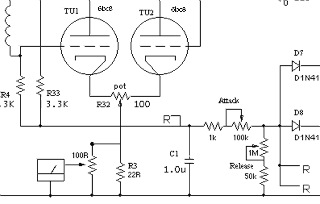
I think I need to do something like this, but I'm not sure where to get small "negative bias"
I quickly tried some BIG negative bias on the meter ground (-15v) and it slammed hardright, so that's headed in the correct direction.
http://en.wikipedia.org/wiki/Shunt_(electrical)#Use_in_current_measuring]http://en.wikipedia.org/wiki/Shunt_(electrical)#Use_in_current_measuring
low side shunt ought to work but no idea how to implement this as yet :-\
tried a resistor in series and a pot setup same as on the high side, but that's not doing the trick yet.
Not sure how to get more range out of the meter either...  R3? or won't this also change my compression amount?  don't want to mess with that too much
DIY-12AU7-meterR1-1.gif

I have NO idea what I'm doing here, but that won't stop me from trying,
so if anybody has a good idea for me please let er rip.
 

Latest posts

Back
Top