You are using an out of date browser. It may not display this or other websites correctly.
You should upgrade or use an alternative browser.
You should upgrade or use an alternative browser.
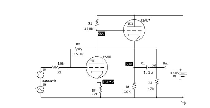
PRR Vari-mu
- Thread starter MikkelM
- Start date


Help Support GroupDIY Audio Forum:
This site may earn a commission from merchant affiliate
links, including eBay, Amazon, and others.

MagnetoSound
Well-known member
Just reduce C8.
Assuming low impedance through the battery V10, R34 gives the load.
Assuming low impedance through the battery V10, R34 gives the load.
buschfsu
Well-known member
trying to add this to the output of my varimu and have a question about gain. if i make the 12ax7 bias resistor 10k variable via pot followed by another 10k resistor to ground (as a voltage div) to could that act as makeup gain or is their not enough gain here to even try to dial it down.
also prr doesn't mention a transformer, i assume the cathode follower takes care of the impedance so to balance i just need 600:600 edcor iron?
also prr doesn't mention a transformer, i assume the cathode follower takes care of the impedance so to balance i just need 600:600 edcor iron?
SIXTYNINER
Well-known member
hey ,
buschfsu
a picture about your va - ri - mu "jewell"
only can be wellcome
cheers
buschfsu
a picture about your va - ri - mu "jewell"
only can be wellcome
cheers
SIXTYNINER
Well-known member
buschfsu said:also prr doesn't mention a transformer, i assume the cathode follower takes care of the impedance so to balance i just need 600:600 edcor iron?
Would love to know that too.
s


![Soldering Iron Kit, 120W LED Digital Advanced Solder Iron Soldering Gun kit, 110V Welding Tools, Smart Temperature Control [356℉-932℉], Extra 5pcs Tips, Auto Sleep, Temp Calibration, Orange](https://m.media-amazon.com/images/I/51sFKu9SdeL._SL500_.jpg)
mylesgm
Well-known member
how do I alter the specified power supply for a 240v mains supply? It doesn't look like I can simply rewire the transformer...
M
M
mac
Well-known member
Hey Myles,
which PSU schematic and power TX are you using?
Mac
which PSU schematic and power TX are you using?
Mac
mylesgm
Well-known member
Hi Mac,
I have an already built unit with a 120v power supply on the original schematic pcb. It uses part of the primary to give the HT for the valves. I've had a hunt through the various threads though and have come up with options for using two transformers and some extra point to point wiring but thats annoying. So instead I'm wondering about putting a 240v to 115v mains transformer inside the case as a step down and using the current powersupply as is. There are a few 240v primary, 115v secondary transformers on ebay at the moment that I thought I might use. Any thoughts on that?
M
mac
Well-known member
Seems a logical approach. The orig schem trafo should be using a multi tap trafo so the 120vAC needed for the 100v b+ is derived from the secondary though - not the primary (mains).
You can also pickup some good multitap "universal" toroidal power trafos on ebay. I got one for my NYD project at the moment which is working out well and has 6 windings. your step down approach may be more cost effective and also alows you to leave the existing psu alone though which could be easier. Just make sure your step down trafo is high enough VA rating.
Mac
mac
Well-known member
Just went looking on Ebay for you and found the one I bought late last year...it is working well in my NYD one bottle - two bottle two channel box....
http://cgi.ebay.com.au/Toroid-Transformer-T30-55W-0-6-3-15-120-200-220-240-260-/220651814235?pt=Vintage_Electronics_R2
;D
might be a more elegant solution to having two lumps of iron in the box?
http://cgi.ebay.com.au/Toroid-Transformer-T30-55W-0-6-3-15-120-200-220-240-260-/220651814235?pt=Vintage_Electronics_R2
;D
might be a more elegant solution to having two lumps of iron in the box?
mylesgm
Well-known member
Ah, I was looking at those, did you use their power supplies as well? They look good.
I'm having a little trouble with the threshold control, the variation between fully clockwise and fully counterclockwise is not large and the meter shows compression with the threshold at either end of the pot throw. I have to reduce the input quite a lot to bring the compression down to only a few db of compression even with the threshold control at fully 'off'. Is there something wrong here or should I sort out some sort of attenuator for the input? I'm driving the comp from the +4 outputs of my lynx aurora.
There also seems to be a little bass frequency loss overall wether the unit is compressing or not. I've added some tamura 1:1 transformers to balance the output of the 5534 and I was wondering if changing the input would significantly alter the tone of the unit or wether the interstage tx is more significant to the tone. If I'm going to change which one would be best or should I change both?
M
mac
Well-known member
Hey Myles, I havent even got my vari-mu working yet so I cant help with those other issues, but was trying to help just in terms of PSU.
I used that trafo with a modified self etch version of gyraf's g9 PSU with a couple of added dropper resistors to power jewel lamps and VU lamps (from old Rola tape decks).
Sure someone else will chime in on the other issues... ;D
Mac
I used that trafo with a modified self etch version of gyraf's g9 PSU with a couple of added dropper resistors to power jewel lamps and VU lamps (from old Rola tape decks).
Sure someone else will chime in on the other issues... ;D
Mac
mylesgm
Well-known member
Well after toying with the vari-mu I've come up with a few things that suited me better than the schematic.
The threshold control seemed to only allow a very small selection of gain reduction. I'm currently using a 100klog and this gives a much wider selection of gain reduction. The heavy reduction will only work for 'effect' compression but I dig that.
The 5534 will of course drive a 600ohm load so I've added a 1:1 transformer here, currently a tamura but that might change, and it sounds great. I do think though that adding a variable output stage is going to be necessary as gain reduction of course reduces the output and if I'm using heavy reduction the gain loss has to be made up somewhere else. Input attenuation is not really necessary though it might be a good addition. In fact I'm considering building a second unit that has a fixed threshold and variable input and output though I'll have to consider how to implement that.
Overall I think this is a great building block for a range of individual specific modifications... Thanks to PRR and the rest who've contributed!
M
mac
Well-known member
The threshold control seemed to only allow a very small selection of gain reduction. I'm currently using a 100klog and this gives a much wider selection of gain reduction. The heavy reduction will only work for 'effect' compression but I dig that.
thats the beauty of DIY ;D sometimes in a room filled with increasingly clean and fat sounding pres and compressors - dirty, harsh or rediculously saturated compression is just what some elements in a track needs!!
mylesgm
Well-known member
lots of my most recent work has been polar opposites, Classical guitar quartet, neumanns and BnK mics with absolute precision with placement, tonal accuracy and ensemble image placement then dirtiest grungy heavy thrash band I've ever heard and they love my driving the comps, eq's, limiters so far in the red and reduction that there is so little definition left except energy. mixing that now actually and I dont think there is one track that is remotely clean. good fun!
mac
Well-known member
awesome  and great to get that variety of work...keeps your ears sharp...and the creativity flowing... Mac
and great to get that variety of work...keeps your ears sharp...and the creativity flowing... MacMatthew Jacobs
Well-known member
I never really got my PRR Vari-mu to work, but this is inspiring. Make me wanna get it out and try and fix it.
I got no signal flowing through. Just buzz and voltages on all the pins of my 5532 and TL074. Still haven't worked out what it could be.
I've checked my solder traces, joints and component placement.
The only component I'm not to sure about is the polarity of the diodes. But this should only affect the sidechain right? I should still be getting a signal through the comp.
Anybody have any ideas what could be wrong?
JD
MagnetoSound
Well-known member
Matthew Jacobs said:... voltages on all the pins of my 5532 and TL074.
I've checked my solder traces, joints and component placement.
What sort of voltages?
Sounds like you may have overlooked a ground connection, unless your chips are blown.
Balanced supply means you should have no significant voltages on the 5532 other than the power rails, and only the 1.5v bias wrt ground on the 074.
Matthew Jacobs
Well-known member
MagnetoSound said:What sort of voltages?Matthew Jacobs said:... voltages on all the pins of my 5532 and TL074.
I've checked my solder traces, joints and component placement.
Sounds like you may have overlooked a ground connection, unless your chips are blown.
Balanced supply means you should have no significant voltages on the 5532 other than the power rails, and only the 1.5v bias wrt ground on the 074.
Hey MagnetoSound, thanks for that.
yeah the voltages are seriously out of whack. With no IC I have +/- 15V more or less on the power rail and nothing on the other pins. Then when I plug in the 5532, one of the power rails drop to like 5V and there are all sorts of voltages (can't remember, but I can measure when I get home) on the other pins. I mean alarming voltages like +6V etc... The voltages all pins on the 074 (apart from power rail) increase rapidly starting at 3V increasing to 6, 8V in 1-2 minutes.
Chips are not blown, cause I swap them round with other gear and they work fine.
Thanks for the advice on checking the ground, I'll definitely do that.
Any other possibilities.
Thanks for the help.
JD
Similar threads
- Replies
- 29
- Views
- 29K