PRR Vari-mu

GroupDIY Audio Forum

Help Support GroupDIY Audio Forum:

This site may earn a commission from merchant affiliate links, including eBay, Amazon, and others.
Tried a few things tonight, not quite there though, with high impedence (500k) pot on the negative side it was easy enough to throw some very low current on the negative side of the meter, that made it possible to zero the meter, but didn't do anything to spread out the range, in fact it decreased the movement of the meter for a given amount of actual gain reduction.
do i need some extra components on the low side, a cap or something (looking at the altec 486 theres a cap coupled to the low side of the meter there. f$%ing mystery to me. shotgun. thinking out loud again.
 
Sleeper, I was adding a tiny amount of bias to the low end of the meter to reduce the swing/dB not increase it.
I was getting too "generous" GR readings on the VU scale. After I biased the low side of the meter, dBGR matched the VU scale pretty close.You sound like you want more swing per dB, so that's the wrong approach for you. Smaller current meter?
 
Hi Larrchild,
Glad you got saw this post. Aaaaahhhhhh Ooooohhhhhhhh I Seeeeeeeeeeeeee.
Well,
Larrchild said:
a tiny amount of bias to the low end of the meter to reduce the swing/dB not increase it.
this is totally confirmed by my experiments here... this is exactly what happened when I added the biasing, I reduced my swing and pushed it to the right.
Ok I've seen your work and I think you know tubes pretty well, so is meter swing a function of voltage swing in the tube?  like the kind of swing we talk about in terms of headroom for instance NO?... like why we need a +-15 powersupply because we have to swing a certain amount of voltage to get the gain reduction to happen. 

As I said, I followed bluebirds mods which mostly involves changing the 22k plate resistors on the 12au7 to 4.7k (as per the UA176 schematic which uses the 6bc8... I've built a couple of tube guitar and hi-fi amps, enough to know that its good practice to present the tubes with an easy load to drive,  I've got a 4 to 1 - 40k to 250 ohm interstage transformer with a 2.2k load resistor facing the tubes, so they are not struggling with the load. I can see that on my scope.
I bet I could make them work a little harder.
It occurs to me that If I raised the plate resistors I might get more voltage swing in the tubes - and pushing harder against the ground and moving the meter a bit more...  Does this seem right?
Hope you have a chance to check this out and can push me one way or the other.
Gotta sleep now, I'll have another go in the morning. Thanks for the info
Kelly
 
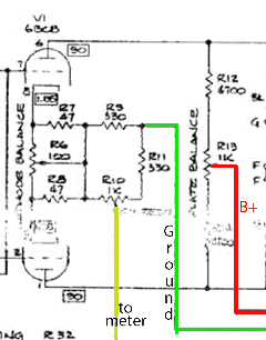
You are measuring the current change of the tubes. The tubes draw maximum current at idle (no GR). When you begin to bias the tubes off with gain reduction, the current of the tubes decreases. this is reflected by the current meter moving downward. It's just a matter of getting the current change you have in this particular circuit to move the correct meter the correct or desired amount.
 
> I can't get the meter to zero out correctly

"Zero gain reduction" is Full Scale.

It might be best to think "Gain": maximum for small signals and less for large signals.

The nominal 12AU7 current at zero GR is 6mA. If you just put a 6mA meter in the cathode link, it would work fine. 6mA at idle and small-signal, 0.5mA at 20dB GR.

You can't get a 6mA meter. Use a 1mA meter and two resistors of roughly 6:1 ratio, the higher one in series with the meter.

That pot scheme SHOULD work. It lets you find an appropriate ratio between tube current and meter current. What is not right about it?
 
Hi PRR 
I guess what I'm thinking is not right is that the 6BC8 tubes I'm using- a la UA 176 are sitting at 500uA (micro) with Zero Gain reduction.  My plate voltages are correct as shown on UA176 schematics and this is more or less exact same topology as your varimu. 
Well maybe I have...
http://scottbecker.net/tube/sheets/106/6/6BC8.pdf
I haven't messed with the 100r pot or R3  22ohm from your design. 
This is the problem right?    I think if I raise raise R3 I should be OK

I guess I'm not up to speed when it comes to reading tube data sheets and figuring out where it should be.
I was thinking the current should be higher at idle but honestly I haven't been able to figure out how to calculate this.  . 

According to the datasheet a class A amplifier with a plate voltage of 150V should have a 220r cathode resistor. max. cathode current is 20 ma.  they say shoot for 70% on cathode bias  14ma
does this sound like the right thing to do in a varimu application, or should we bias a bit higher? lower?

With a 100Volts on the plates the UA has 330r+ 47r (well sort of, 47R in parallel with whatever part of the cathode trim pots null resistance)

I'll keep on reading. 
Thanks for the great project. 
Sleeper     
UA176cut.gif

 
therecordingart said:
Anyone have links to the Bluebird mods?  I couldn't find them by searching.

Search for: prr by user: bluebird

First hit: http://www.groupdiy.com/index.php?topic=28183.0

JDB.
[links appear to be gone, but the description should give you all you need]
 
Hi,

Just got a PCB for this and getting ready to start building. Have a few "newbie" questions. I've only built one other tube circuit before (a 12AX7 preamp from EM, which distorts mostly and may have been designed that way -- ok for a Van Halenesque fuzzy sound but otherwise....) but have built successfully many, many, PAIA kits.... Anyway I am thoroughly confused on the stereo strapping of this. Reading the Kent post and the original PRR post, it seems you bypass the RC network for one channel's cv. Kent says to jumper "from attack of channel 2 to a position after " 1k resistor. But PRR states that C1 and the Attack Release resisitor/pots are shared. I am a bit confused, if you just install that jumper what does the TL074 then do it doesn't appear to be connected to anything or do you jumper like this: red being the jumper referenced in the text red and green being what i understand from reading the original design notes.  ??? Also, the prototype seems to have just one meter, which makes sense but which channel does it go with or does it matter, and can i just eliminate the pot for that other channel? And am I correct in reading above that the meter should be FS if there is no Gain Reduction?  THANKS!
 

Attachments

  • stereo_question.gif
    stereo_question.gif
    25.4 KB · Views: 258
Hi there,

well, during collecting the components for a Vari Mu, a couple of questions have risen.... Some might be pretty stupid, haha ! ;D

-1/4 watt resistors will be fine except where noted different ?

-the 1K pot, is it a logarithmic ?

-I can't find a suitable 240-120 v transformer. So I was thinking to buy a normal 30VA 240/12-0-12 toroid, and use a 240/6-0-6 in reverse to get the desired 120 volt. (or will this be idiotic ?). I've got a small one laying here (15 VA). Will this one do ? I suppose so, but I'd like to be sure.

-I'm going to use an 10k/10k inputtransformer with the 10kpot for +4dB operation. Could I use Keith's output balancing board for the 9k pre for getting the signal loud enough for +4dB operation? Or would the outputcircuit of the GSSL be better (or hotter) ?

-ehhhhh, there was another question, but now I can't recall what it was, hahaha.
 
helterbelter said:
-I can't find a suitable 240-120 v transformer. So I was thinking to buy a normal 30VA 240/12-0-12 toroid, and use a 240/6-0-6 in reverse to get the desired 120 volt.

That will get you either 240 or 480 volts, no?
 
I can answer a couple of questions

1k pot- I used linear - no problems with the "feel" 
you are feeding sidechain so it's not like there's a direct logarhythmic correlation to what you hear.

I used mostly 1/4 watts no problems. I think in the power supply there are some other rated resistors. 
I used all 1/2 watt there, but that's because I had them, not because I needed to.

switches are not specified. I read a lot of discussion in LA2A and pultec EQ threads about shorting or non-shorting switches and in the end there doesn't seem to be any definite conclusions. These are sidechain values being switched so as far as I can tell there is no immediate and certain danger of loud pops (which would probably be the case if this were signal switching)

Using a shorting switch you would end up briefly with caps in parallel which is probably better than having no capacitance in the circuit for that microsecond between switch poles which occurs with the shorting version.
I have shorting in mine. I like em.
good luck on the build
 
MagnetoSound said:
helterbelter said:
-I can't find a suitable 240-120 v transformer. So I was thinking to buy a normal 30VA 240/12-0-12 toroid, and use a 240/6-0-6 in reverse to get the desired 120 volt.

That will get you either 240 or 480 volts, no?

::) Yes, of course, 480.... how dumb of me,  I knew I had a stupid question ! (head banging against the wall...)

But a 240 : 24-0-24 in reverse should do, right ? will a 15VA do ?  And the 240 : 12-0-12 in front, will 30va suffice ?


Sleeper said:
I can answer a couple of questions

1k pot- I used linear - no problems with the "feel"  
you are feeding sidechain so it's not like there's a direct logarhythmic correlation to what you hear.

I used mostly 1/4 watts no problems. I think in the power supply there are some other rated resistors.  
I used all 1/2 watt there, but that's because I had them, not because I needed to.

switches are not specified. I read a lot of discussion in LA2A and pultec EQ threads about shorting or non-shorting switches and in the end there doesn't seem to be any definite conclusions. These are sidechain values being switched so as far as I can tell there is no immediate and certain danger of loud pops (which would probably be the case if this were signal switching)

Using a shorting switch you would end up briefly with caps in parallel which is probably better than having no capacitance in the circuit for that microsecond between switch poles which occurs with the shorting version.
I have shorting in mine. I like em.
good luck on the build


Ah, sidechain, okay, cool. So, when using non-shorting lorlins, it means that the compression will be turned of very briefly while switching, right ?............ I'm not sure if this will be bothering me. I have a pile of non-shorting lorlins, but on the other hand, a few shorting lorlins won't cost that much either....


Thank you both for the replies !
 
Hi folks, new guy here but long-time follower of this and many other threads.  PRR, if I haven't missed it somewhere else, could you kindly say a few words about the 1k resistor (R30) connected between the 12AU7 plates on the original schematic?  You do mention driving U3 with a 1k source impedance for low noise and R30 will certainly reflect this to the secondary side (in parallel with transformer parasitics and the output impedance of the 12AU7 differential stage, which will most certainly vary with gain reduction on account of changing plate resistance), but it would appear that this would be equivalent to a 500-ohm load on each plate since the AC signals are of opposite polarity.  Is this very low shunt impedance a necessary part of the gain-reduction action?  I seem to remember a thread where you talk about variable-mu compressor theory and it's not just the changing mu that lowers the gain, it's also the rising rp as the plate curves flatten at high bias...and maybe the very low shunt impedance is part of this concept.  The balanced operation will cancel much of the (asymmetrical) distortion caused by the 500-ohm load on each plate, but could you please comment on this a bit?
 
Hey guys - I just found the answer to my own question here (http://www.groupdiy.com/index.php?topic=3438.0):

"The load must be greater than the maximum (low-gain) plate resistance, or less than the minimum (hi-gain) plate resistance. In this case, either over 300KΩ, or under about 2KΩ. Fairchild went hi-Z by using a bunch of tubes to lower the plate resistance (and still it needs a pretty fancy winding). I went low-Z for low-price: $100 versus $10,000. The disadvantage of the low-Z loading is low tube gain, but gain is cheap today: that 5532 output stage costs $2."

Makes sense to me.  Also makes sense why many old limiters used interstage transformers connected to another set of push-pull grids which negligibly loaded the plates...which would be the hi-Z approach.  PRR, you rule!
 
do you guys think these would work for this?  cheap as hell, but the freq response according to the listing looks pretty shabby.  i was just wondering if anybody that has used the older radio shack isolation transformers recognized this or if they were different.

http://cgi.ebay.com/Radio-Shack-Audio-Isolation-Transformers-1-1Turns-Ratio_W0QQitemZ180429658736QQcmdZViewItemQQptZLH_DefaultDomain_0?hash=item2a02721a70

guess it would only hurt me around $5 to find out!
 
> these would work for this?

Those are modem transformers.

You want Car Audio transformers.

Ground Loop Isolator
$16.99
Catalog #: 270-054
Online:  In stock
Usually ships in 1 - 2 business days 
http://www.radioshack.com/product/index.jsp?productId=2062214
 
Back
Top