SB4000 Support Thread

GroupDIY Audio Forum

Help Support GroupDIY Audio Forum:

This site may earn a commission from merchant affiliate links, including eBay, Amazon, and others.
ruckus328 said:
sheadstedford said:
Any one got any wiring instructions for this badboy?
Im going by the pics in the assembly doc but just wanna make sure im doing it right
???

Shead, not sure what you're after - the build manual lists what ever pin on every connector is for.  Is there a particular spot you're confused on?

Dont worry its sorted mate!
Thanks!!!!!
 
gandhalf3 said:
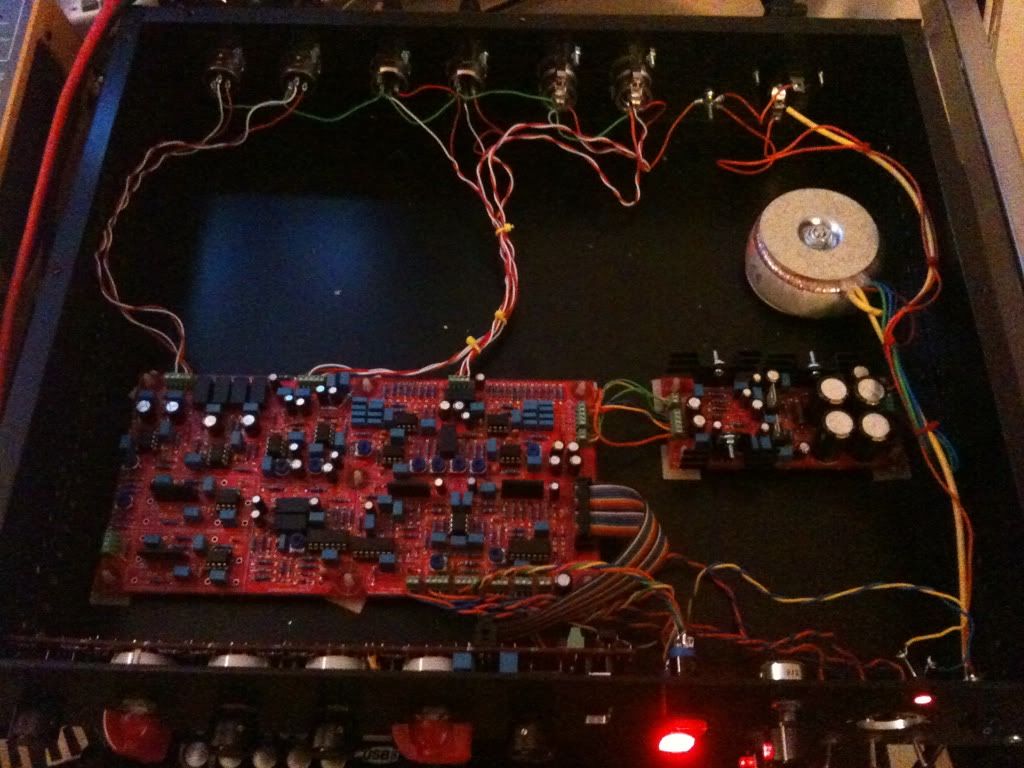
hello, nothing is grounded yet, because the chassis is not there.

gandhalf, STOP.  Do not pass go, do not collect $200.  Do not turn on the unit again.  Disconnect your AC line.

THE SYSTEM MUST BE GROUNDED

You have everything floating.  This is dangerous - to You and the PCB.

Hopefully you have not damaged anything.  Your mains ground, PCB ground, and XLR Pin 1's need to be tied together whether it's in a chassis or not.  You probably have all kinds of voltage potentials going on.  Not surprised it sounds like a shotgun when those relays switch.  You'll probably have some sort of little click when the bypass is engaged as it's the nature of 8 sets of relay contacts closing, but it shouldn't be be loud, nasty, or bursting at all.  The other relays you mentioned aren't switching audio, which is why you're not hearing them pop - but they're probably not happy right now either.

Most likely your electrolytic capacitors are probably all sitting there charged up because the charge has nowhere to go.  With the unit turned off, check all 5 of your voltage rails, if they're not reading less than 1V, then you need to bleed them out - connect something like a 1M (highest wattage you have) resistor between the PCB ground and mains ground and let it sit for a little bit.  Just to be on the safe side, use insulated pliers, don't touch the resistor with your hands (I'm paranoid like that).  Of course in order for this to work you'll need to reattach your AC cord so that the PCB ground has a path to your earth ground.  I would hook the resistor up first and then plug in the AC line.

Check your voltage rails with a multimeter, make sure they're not charged up.  WITH YOUR AC LINE CORD DISCONNECTED - Tie your IEC ground, PSU ground, and xlr pin 1's all together - you can just run a wire from each point and temporarily connect them with a wire nut or solder them all together - whatever you have to do.

Just please be careful.  If you're not clear on what needs to be done please let me know, I can help you via AIM, etc.


Has anyone made any headway by cramming the CnB pot in this chassis?  It was discussed a few pages back:

http://www.groupdiy.com/index.php?topic=40971.100

Will the 3rd party CnB board be needed - or just the pot?  And does the SB4000 have the correct power available to power the CnB board (if needed)?  If this is overly complicated and too tight for this already crammed build - I'll just do an external CnB with a second DAW route straight through the AD/DA's and blend Crushed and Dry tracks in the DAW...

Thanks!
 
Many of the EPCOS capacitors that are rated at 63V seem to be out of stock for a long time, is it OK to replace them with 100V capacitors? The 100V capacitors are about 10mm wide instead of 7.5mm.
 
SimonB said:
Many of the EPCOS capacitors that are rated at 63V seem to be out of stock for a long time, is it OK to replace them with 100V capacitors? The 100V capacitors are about 10mm wide instead of 7.5mm.

No harm in 100V but it's probably going to be pretty tight in alot of spots, especially the T1/T2 filter sections.  You could probably cram them in but it would involve alot of bending parts out of the way of other parts, the footprints weren't designed for 10mm parts so I'd really advise against it.  They don't have to be epcos - wima, vishay, bc components, kemet, any of those would be fine.  I just did a quick check at mouser on a couple of the values and the couple I checked had thousands in stock.
 
Just noticed what seems to be an error in Mike's build doc with regards to the pilot holes for mounting the front panel to the chassis...for my par-metal chassis I had to use the INNER most set...please verify before drilling.
 
Ptownkid said:
Just noticed what seems to be an error in Mike's build doc with regards to the pilot holes for mounting the front panel to the chassis...for my par-metal chassis I had to use the INNER most set...please verify before drilling.
Please can you elaborate this? Can somebody post the revision of the building doc?
 
Guys, this is in regards to the pre-drilled pilot holes that are present on MY front panels.  If you didn't get a front panel from me, then disregard, it doesn't affect you.  Build manual has been corrected.
 
Jus turned the power on and it Works!!!!
Im getting a pretty annoying hum tho when i push the compressor button in.
Everything is grounded to the star ground point.
I have literally just hooked it up tho so i am gonna have a play and do some calibrating.

The main thing i that IT WORKS!!!!!
;D
 
Congrats!

Hum...hmm, did you do any mods to it?  I remember you were going to do something with a tube circuit.  It should be dead quiet, mine has excess -90dbu noise floor.

Pics?  Might help me spot something.
 
<a href="http://s1085.photobucket.com/albums/j435/sheadstedford/?action=view&amp;current=44beb9d5.jpg" target="_blank"><img src="http://i1085.photobucket.com/albums/j435/sheadstedford/44beb9d5.jpg" border="0" alt="Photobucket"></a>

Heres teh guts, sorry its from my camera phone

<a href="http://s1085.photobucket.com/albums/j435/sheadstedford/?action=view&amp;current=d6e91e2c.jpg" target="_blank"><img src="http://i1085.photobucket.com/albums/j435/sheadstedford/d6e91e2c.jpg" border="0" alt="Photobucket"></a>

Heres teh plain fron without markings or meter (on its way)

my lorlin switches seem to not want to stick to their positions, like one minute the ratio has 3 positions like it should, then the next its spinning a fulll circle of positions?????
 
44beb9d5.jpg


d6e91e2c.jpg
 
Well happy its working but gotta wait for the meter so i can accurately calibrate stuff, doesnt really sound like any changes are happening when i turn switched ratios or turn up threshold and cant see any GR as waiting for the meter, should be here soon tho, i know ptownkid is doing his best for us.
For some reason my lorlin switches keep turning past there stop point which is strange and annoyin as i now dont know what position is what....any ideas why this is?
(dodgy switches maybe) not turned much tho so im sure they are top notch.
If anyone has built one of these already and has any of the same problems let me know!!
Shout to rukus and ptown!!!
Well chuffed
 
Hi Shea-nice work.
Looks really oldschool. Can i rent some of that space?

Mike,
My resistors for R160 & 165 are a bit off, they are suppose to be 510K but are 511 according to colors and measures at 516K.
Does it matter, or a classic case of newbie paranoia?

Its slowly taking shape...

Cheers
Rune
 
Ptownkid said:
Good Job Shea!!!

Rellister, no big deal, that is only off by 1%.

Yes ptown!
Are my lorlins normal doing wat they do?
Im worrying my little
Newwb head off.

Are the meters still on for shippin friday???
 

Latest posts

Back
Top