SB4000 Support Thread

GroupDIY Audio Forum

Help Support GroupDIY Audio Forum:

This site may earn a commission from merchant affiliate links, including eBay, Amazon, and others.
Sorry for some reason hitting enter submitted the form last post...

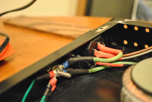
The Brown and grey together GO TO N on the IEC
The Blue and Purple tie together goes to the  OTHER(not center) pole on the on/off switch (you may have to tie an extra lead on there to get the length needed)
Ground goes to Ground
The center of the on/off switch goes to the L on the IEC

Please don't blow yourself up! :)  Burned flesh doesnt smell good....i should know... :-[


ONLY use the solder lugs on the IEC.  Dont connect anything to a place where it doesnt look like something should be soldered to.

edit: that area that boxed off in your drawing (on the right of the IEC) dont connect anything to that, just use the lugs on the left.  If your ON/OFF switch has 3 pins, one of them (either top or bottom) will be left unused.
 
sr1200 said:
Sorry for some reason hitting enter submitted the form last post...

The Brown and grey together GO TO N on the IEC
The Blue and Purple tie together goes to the  OTHER(not center) pole on the on/off switch (you may have to tie an extra lead on there to get the length needed)
Ground goes to Ground
The center of the on/off switch goes to the L on the IEC

Please don't blow yourself up! :)  Burned flesh doesnt smell good....i should know... :-[


ONLY use the solder lugs on the IEC.  Dont connect anything to a place where it doesnt look like something should be soldered to.

edit: that area that boxed off in your drawing (on the right of the IEC) dont connect anything to that, just use the lugs on the left.  If your ON/OFF switch has 3 pins, one of them (either top or bottom) will be left unused.

Okay, I've removed that last diagram to avoid someone getting bad advice. I think this is right now.

Thanks for the help!


Attachments

  • tranformerIECwiring3.jpg
    tranformerIECwiring3.jpg
    45.6 KB
drjoe said:
wave said:
drjoe,
Thanks for the input. I chopped mine.
It seems like you and I sourced the parts ourselves. I was wondering, did you get STMicro regulators (mouser # 511-L7912ACV)?
I did and then I read this support thread. Seems people were having problems with the 7912 VOLTAGE REGULATOR made by STMicro.

Yeah, I sourced myself. I just barely missed out on the kits and hadn't heard about the upcoming kit until after my purchase. I'm happy I went through the trouble though since I learned a lot in the process. Looks like I did end up with the problematic STMicro regulators. I remember reading that part of the thread many times and still missed it on the BOM. I was able to find equivalents for almost every part, but I did end up going with THAT2180C instead of THAT2181C VCA.

Have you tested your unit yet? Are you ordering replacements? I think Ruckus straight up said to replace them even if they work because eventually they will fail.

I'm still building my unit so no testing yet. I did order new regulators. I figured I 'm better off replacing a part that is known to have issues.
What is the difference in the 2180s?
 
wave said:
drjoe said:
wave said:
drjoe,
Thanks for the input. I chopped mine.
It seems like you and I sourced the parts ourselves. I was wondering, did you get STMicro regulators (mouser # 511-L7912ACV)?
I did and then I read this support thread. Seems people were having problems with the 7912 VOLTAGE REGULATOR made by STMicro.

Yeah, I sourced myself. I just barely missed out on the kits and hadn't heard about the upcoming kit until after my purchase. I'm happy I went through the trouble though since I learned a lot in the process. Looks like I did end up with the problematic STMicro regulators. I remember reading that part of the thread many times and still missed it on the BOM. I was able to find equivalents for almost every part, but I did end up going with THAT2180C instead of THAT2181C VCA.

Have you tested your unit yet? Are you ordering replacements? I think Ruckus straight up said to replace them even if they work because eventually they will fail.

I'm still building my unit so no testing yet. I did order new regulators. I figured I 'm better off replacing a part that is known to have issues.
What is the difference in the 2180s?

I'm not sure about the difference between the 2181s vs. 2180s, but I know that they're interchangeable. I've heard that there is no discernable difference, but maybe someone with more knowledge could give a better answer.

Which regulator did you go with? (mouser part #)
 
jandoste said:
sr1200 said:
Just a note, the fix i posted isnt really a fix for anyone in the future... all it does is put the unit back in phase when it ISNT bypassed, when you bypass it will be out of phase again, (theres a little trick to use the ext side chain w. nothing plugged in to bypass instead of the big red buttons)  just wanted to throw that out there.  I never have the unit in the chain when im not using it anyway so for me its not a biggie, i just un-patch the beast.

Hey Guys,
I'm only one that I got this phase?
I still have the phase problem! I have checked everything but got it  :eek:
Thanks for any advice...

Ruckus? any idea? I have checked it today but not found the phase solution...
:eek:
 
drjoe said:
wave said:
drjoe said:
wave said:
drjoe,
Thanks for the input. I chopped mine.
It seems like you and I sourced the parts ourselves. I was wondering, did you get STMicro regulators (mouser # 511-L7912ACV)?
I did and then I read this support thread. Seems people were having problems with the 7912 VOLTAGE REGULATOR made by STMicro.

Yeah, I sourced myself. I just barely missed out on the kits and hadn't heard about the upcoming kit until after my purchase. I'm happy I went through the trouble though since I learned a lot in the process. Looks like I did end up with the problematic STMicro regulators. I remember reading that part of the thread many times and still missed it on the BOM. I was able to find equivalents for almost every part, but I did end up going with THAT2180C instead of THAT2181C VCA.

Have you tested your unit yet? Are you ordering replacements? I think Ruckus straight up said to replace them even if they work because eventually they will fail.

I'm still building my unit so no testing yet. I did order new regulators. I figured I 'm better off replacing a part that is known to have issues.
What is the difference in the 2180s?

I'm not sure about the difference between the 2181s vs. 2180s, but I know that they're interchangeable. I've heard that there is no discernable difference, but maybe someone with more knowledge could give a better answer.

Which regulator did you go with? (mouser part #)

863-MC7912ACTG
ON Semi Linear Regulators - Standard
12V 1A Negative

863-MC7812ACTG
ON Semi Linear Regulators - Standard
12V 1A Postive
 
jandoste said:
jandoste said:
sr1200 said:
Just a note, the fix i posted isnt really a fix for anyone in the future... all it does is put the unit back in phase when it ISNT bypassed, when you bypass it will be out of phase again, (theres a little trick to use the ext side chain w. nothing plugged in to bypass instead of the big red buttons)  just wanted to throw that out there.  I never have the unit in the chain when im not using it anyway so for me its not a biggie, i just un-patch the beast.

Hey Guys,
I'm only one that I got this phase?
I still have the phase problem! I have checked everything but got it  :eek:
Thanks for any advice...

Ruckus? any idea? I have checked it today but not found the phase solution...
:eek:

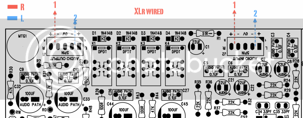
You need to do the phase mod as indicated in the build manual, otherwise your unit will be out of phase when the compressor is engaged.  If you have done this mod, and your unit is out of phase, then you wired your xlr's wrong.

I'm confused, didn't you complete your unit a year ago?
 
ruckus328 said:
You need to do the phase mod as indicated in the build manual, otherwise your unit will be out of phase when the compressor is engaged.  If you have done this mod, and your unit is out of phase, then you wired your xlr's wrong.

I'm confused, didn't you complete your unit a year ago?

Thanks Ruckus,
Yes, I finished my unit a year ago as I said before I completed the unit but not calibration...
XLR's wire is not wrong I also have checked them...
SB4000.png


Solid vs stranded wire for hookup.
Any thoughts?

I'm asking b/c I got some 20awg 8 conductor wire for hookup. It is multicolored and would be perfect but upon further inspection I noticed it is solid. Is there any difference aside from malleability?

Yes I'm a noob.

Thanks
 
jandoste said:
ruckus328 said:
You need to do the phase mod as indicated in the build manual, otherwise your unit will be out of phase when the compressor is engaged.  If you have done this mod, and your unit is out of phase, then you wired your xlr's wrong.

I'm confused, didn't you complete your unit a year ago?

Thanks Ruckus,
Yes, I finished my unit a year ago as I said before I completed the unit but not calibration...
XLR's wire is not wrong I also have checked them...
SB4000.png

Fixed!
I built two XLR cables and one of them was wrong :)
So we are learning:) :)
 
A friend of mine told me to be careful transporting the unit because the trimpots can shake and change value, thus requiring re-calibration.

Could the trimpots be superglued in place to avoid this? Is this a bad idea for reasons other than having to replace the trimpot to accomodate for future changes in the circuit?

I just superglued all of my rivets to avoid the pins popping out into the unit and this idea crossed my mind.
 
I guess the same would go for every other piece of studio equipment then, I have yet to see one that DOESNT have a trim pot.  Personally i dont think they're going to get that "out of cal" from transporting... but i also wouldnt leave it unracked in the back seat whilest driving through the australian outback in a dune buggy....
 
I just tried powering up for the first time. I'm not sure if I'm measuring the rails correctly.

I'm getting the same voltages whether the unit is on or off. When I connect the main board and control board and power up, nothing happens.

You can see my transformer wiring a few posts back.

No LED, no bargraph, no VU movement.
 

Attachments

  • AifyOioCIAAX58m.jpg
    AifyOioCIAAX58m.jpg
    194.3 KB
disconnect the PS from the rest of the unit and see what voltages youre getting on the rails with nothing hooked up.  If its good, then add the Main PCB and check the rails again, if its still good, add the front panel board.  This will help you determine where the issue may lie. (i believe this was discussed quite a few pages back by Ruck)
 
I think my problem is with the wiring of the transformer and switch. Can someone verify that it's correct? I'm not getting any readings on the power supply.

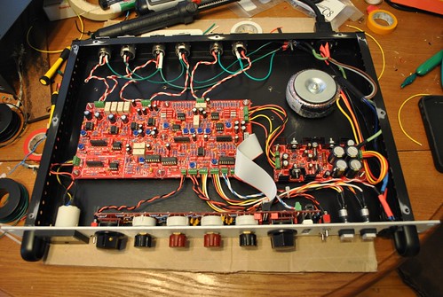
I was testing continuity to make sure the connections were solid and I caught a spark near the IEC. I don't want to blow myself up so I won't plug it in again until my wiring is verified. I posted the diagram a few posts back. I'm attaching a better photo of my completed unit. Thanks.

6649804237_299fab330b.jpg

6649823243_a312c03765.jpg

 
wave said:
Another one finished!
Voltages look good! On to calibration.

Nice! I like the funky straight bend wiring between the boards.

Wish I had the same luck with the voltages checking out. Thanks for the photo.
 
ruckus328 said:
Bieck-

Check for backwards diodes around the TL072 & on control board.  Check tantalum caps are correct orientation on control board.  Check TL072 orientation.  If you send a mono signal to the right channel, and then left channel, and get the same issue as you described, the problem lies somewhere after the sidechaining summing point (which starts at the input to the attack timing resistors).  Somewhere from that point on is where your problem lies, on schematic look at bottom center and bottom right side for circuitry involved.

Thanks for your help Ruckus!!  You are awesome  :)

Well, I checked everything on the control board, and around TL072 and fixed a few more solder joints and it's working way better but still not perfect.  I've been studying the schematic, BTW it's such an awesome design.  Great job!!  :)  I installed the 47k resistor, and removed the jump by the threshold pot.  That helps and reduces the problem a lot, but lowers the threshold sensitivity too much, so I might replace it with a lessor resistor (experiment with different values)??

I noticed that now, I can not create the slamming transient issue when the compressor is in Auto release mode.  :)  So that seems like a good thing!!  It only freaks out in the other release settings, and now only when the compressor is compressing at least 10+dB of compression??? 

Do you think I should purchase a few replacement op chips to try, some TL072s?  Do you, or any one, have any additional thoughts??

really appreciate all the genius advice, and guidance, I was totally stuck, and now it works much better!!
thx
greg
 
drjoe said:
sr1200 said:
Sorry for some reason hitting enter submitted the form last post...

The Brown and grey together GO TO N on the IEC
The Blue and Purple tie together goes to the  OTHER(not center) pole on the on/off switch (you may have to tie an extra lead on there to get the length needed)
Ground goes to Ground
The center of the on/off switch goes to the L on the IEC
edit: that area that boxed off in your drawing (on the right of the IEC) dont connect anything to that, just use the lugs on the left.  If your ON/OFF switch has 3 pins, one of them (either top or bottom) will be left unused.
index.php

If your mains switch from your drawing has 3 pins, it might be an illuminated mains switch ? If so, wiring will be different from description above and 'L' from IEC will go to the outer (bigger) pin of your switch, center (bigger) pin of your switch goes to your transformer and the remaining (smaller) pin of your switch goes to IEC 'N', so the neon inside the switch shows up with mains present and switch in its 'ON' position.

I just tried powering up for the first time. I'm not sure if I'm measuring the rails correctly.
I'm getting the same voltages whether the unit is on or off. When I connect the main board and control board and power up, nothing happens.
You can see my transformer wiring a few posts back.
No LED, no bargraph, no VU movement.

I think my problem is with the wiring of the transformer and switch. Can someone verify that it's correct? I'm not getting any readings on the power supply.
I was testing continuity to make sure the connections were solid and I caught a spark near the IEC. I don't want to blow myself up so I won't plug it in again until my wiring is verified. I posted the diagram a few posts back. I'm attaching a better photo of my completed unit.
Confirm, your transformer is getting AC mains voltage with mains switch 'ON' by setting your multimeter for measuring Voltages of AC in a range greater your expected local mains voltages (probably setting 200VAC). Black probe to the multimeters COM port, red probe to the V or ohms port. With your mains wire plugged in, probing voltage reading between your transformer mains wires will be about 115VAC. Case not, activate the mains switch to its 'OFF' position and measure again. Voltage now present? pull yours mains wire off the wall and take your connection between transformer and switch to the other throw side of the switch or turn the switch around. Still no voltage present? exchange the blown fuse inside your fused IEC socket.
Now set your multimeter for a DC voltage reading in the probably 20VDC range, keep the black probe at a 0V connection on pcb or at your star-ground for further measurements and probe the +15VDC, -15VDC, +12VDC and -12VDC rail voltages with your red probe wire for confirmation.
Good luck.
 
Back
Top