SB4000 Support Thread

GroupDIY Audio Forum

Help Support GroupDIY Audio Forum:

This site may earn a commission from merchant affiliate links, including eBay, Amazon, and others.
drjoe said:
I think my problem is with the wiring of the transformer and switch. Can someone verify that it's correct? I'm not getting any readings on the power supply.

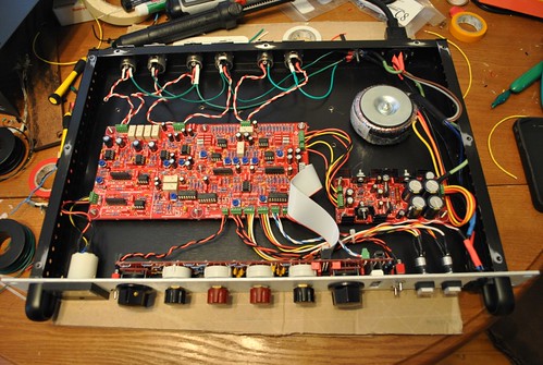
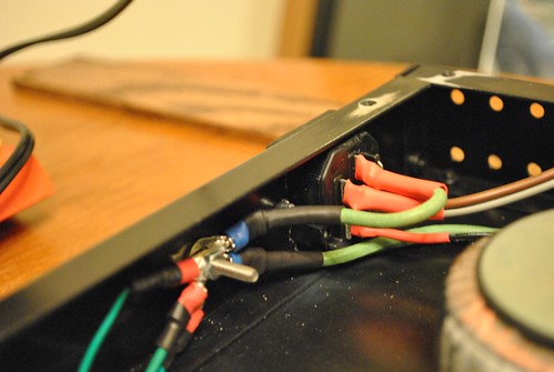
I was testing continuity to make sure the connections were solid and I caught a spark near the IEC. I don't want to blow myself up so I won't plug it in again until my wiring is verified. I posted the diagram a few posts back. I'm attaching a better photo of my completed unit. Thanks.

6649804237_299fab330b.jpg

6649823243_a312c03765.jpg

Look at my power switch in my photo.
The blue and violet are tied to center pin.
The green wire tied to the bottom pin of the switch (I used green b/c it was extra 14 awg wire and I didn't have any black in that guage NOT BECAUSE THAT IS GOING TO THE GROUND!!!) goes to the "L" terminal of the IEC.

I looked at your photo and your brown and gray are tied to the correct pin of your IEC
 
Your live feed should go to an outside pin and your blue/violet tie should go to the center pin. That way there's not live mains voltage present at the extra outside pin when the switch is in the off position
 
drjoe said:
wave said:
Another one finished!
Voltages look good! On to calibration.

Nice! I like the funky straight bend wiring between the boards.

Wish I had the same luck with the voltages checking out. Thanks for the photo.

Thanks!
I used some soild core wire for that and it literally took my like 2 hours of fitting, bending and straightening to get it like that!
 
Harpo said:
I think my problem is with the wiring of the transformer and switch. Can someone verify that it's correct? I'm not getting any readings on the power supply.
I was testing continuity to make sure the connections were solid and I caught a spark near the IEC. I don't want to blow myself up so I won't plug it in again until my wiring is verified. I posted the diagram a few posts back. I'm attaching a better photo of my completed unit.
Confirm, your transformer is getting AC mains voltage with mains switch 'ON' by setting your multimeter for measuring Voltages of AC in a range greater your expected local mains voltages (probably setting 200VAC). Black probe to the multimeters COM port, red probe to the V or ohms port. With your mains wire plugged in, probing voltage reading between your transformer mains wires will be about 115VAC. Case not, activate the mains switch to its 'OFF' position and measure again. Voltage now present? pull yours mains wire off the wall and take your connection between transformer and switch to the other throw side of the switch or turn the switch around. Still no voltage present? exchange the blown fuse inside your fused IEC socket.
Now set your multimeter for a DC voltage reading in the probably 20VDC range, keep the black probe at a 0V connection on pcb or at your star-ground for further measurements and probe the +15VDC, -15VDC, +12VDC and -12VDC rail voltages with your red probe wire for confirmation.
Good luck.

Thanks for the detailed instructions. It must be a bad fuse, but it checks good for continuity. Doesn't that mean it's okay?

I'm measuring 122-124VAC at the IEC between hot and cold, but nothing at the transformer mains.

I'll pick up a new fuse tonight.

wave said:
Your live feed should go to an outside pin and your blue/violet tie should go to the center pin. That way there's not live mains voltage present at the extra outside pin when the switch is in the off position

Thanks. My switch was wired backwards, (On was Off) so when I fixed that I also changed the wiring to have the blue/violet on the center pin. Also used a thicker gauge wire for the connection to the fuse. Now my unit is wired just like your photo. Thanks!

 
Ruckus,
I seem to be having an issue with my ratios.
They seem to be behaving in reverse. I.E. 2:1 gives me more compression than 10:1


EDIT: Although this thing sounds so good I'm not sure how much it matters. WOW.
 
Harpo said:
I think my problem is with the wiring of the transformer and switch. Can someone verify that it's correct? I'm not getting any readings on the power supply.
I was testing continuity to make sure the connections were solid and I caught a spark near the IEC. I don't want to blow myself up so I won't plug it in again until my wiring is verified. I posted the diagram a few posts back. I'm attaching a better photo of my completed unit.
Confirm, your transformer is getting AC mains voltage with mains switch 'ON' by setting your multimeter for measuring Voltages of AC in a range greater your expected local mains voltages (probably setting 200VAC). Black probe to the multimeters COM port, red probe to the V or ohms port. With your mains wire plugged in, probing voltage reading between your transformer mains wires will be about 115VAC. Case not, activate the mains switch to its 'OFF' position and measure again. Voltage now present? pull yours mains wire off the wall and take your connection between transformer and switch to the other throw side of the switch or turn the switch around. Still no voltage present? exchange the blown fuse inside your fused IEC socket.
Now set your multimeter for a DC voltage reading in the probably 20VDC range, keep the black probe at a 0V connection on pcb or at your star-ground for further measurements and probe the +15VDC, -15VDC, +12VDC and -12VDC rail voltages with your red probe wire for confirmation.
Good luck.

I've replaced my fuse. For transformer mains I'm probing between blue/violet's connection to the switch & brown/grey's connection to IEC. I get no voltage with unit on or off. The only voltage I'm able to measure is from the 122V between the pins of the IEC. I get the proper continuity between connections when turning the switch on and off.

Getting nothing between GND & +/-12VDC or +/-15VDC rails.

I'm only seeing fractions of a volt on the power supply:

0.42V between +Rail (TP15) & GND
-0.33V between -Rail (TP13) & GND
0.73V between +Rail & -Rail

I get these readings whether the unit is on or off.

What are the chances I have a bad transformer? Should I probe between the black, red, orange, and yellow wires? I think I've covered all other bases and my wiring has been checked and double checked.
 
drjoe said:
Harpo said:
I think my problem is with the wiring of the transformer and switch. Can someone verify that it's correct? I'm not getting any readings on the power supply.
I was testing continuity to make sure the connections were solid and I caught a spark near the IEC. I don't want to blow myself up so I won't plug it in again until my wiring is verified. I posted the diagram a few posts back. I'm attaching a better photo of my completed unit.
Confirm, your transformer is getting AC mains voltage with mains switch 'ON' by setting your multimeter for measuring Voltages of AC in a range greater your expected local mains voltages (probably setting 200VAC). Black probe to the multimeters COM port, red probe to the V or ohms port. With your mains wire plugged in, probing voltage reading between your transformer mains wires will be about 115VAC. Case not, activate the mains switch to its 'OFF' position and measure again. Voltage now present? pull yours mains wire off the wall and take your connection between transformer and switch to the other throw side of the switch or turn the switch around. Still no voltage present? exchange the blown fuse inside your fused IEC socket.
Now set your multimeter for a DC voltage reading in the probably 20VDC range, keep the black probe at a 0V connection on pcb or at your star-ground for further measurements and probe the +15VDC, -15VDC, +12VDC and -12VDC rail voltages with your red probe wire for confirmation.
Good luck.

I've replaced my fuse. For transformer mains I'm probing between blue/violet's connection to the switch & brown/grey's connection to IEC. I get no voltage with unit on or off. The only voltage I'm able to measure is from the 122V between the pins of the IEC. I get the proper continuity between connections when turning the switch on and off.

Getting nothing between GND & +/-12VDC or +/-15VDC rails.

I'm only seeing fractions of a volt on the power supply:

0.42V between +Rail (TP15) & GND
-0.33V between -Rail (TP13) & GND
0.73V between +Rail & -Rail

I get these readings whether the unit is on or off.

What are the chances I have a bad transformer? Should I probe between the black, red, orange, and yellow wires? I think I've covered all other bases and my wiring has been checked and double checked.

I would.
Put your com probe on the star ground and your V probe on the little screws that hold the xfrmr wires into the green connector.
If I do that, I get 20V AC on the black and yellow.
 
drjoe said:
I've replaced my fuse. For transformer mains I'm probing between blue/violet's connection to the switch & brown/grey's connection to IEC. I get no voltage with unit on or off. The only voltage I'm able to measure is from the 122V between the pins of the IEC. I get the proper continuity between connections when turning the switch on and off.

Getting nothing between GND & +/-12VDC or +/-15VDC rails.

I'm only seeing fractions of a volt on the power supply:

0.42V between +Rail (TP15) & GND
-0.33V between -Rail (TP13) & GND
0.73V between +Rail & -Rail

I get these readings whether the unit is on or off.

What are the chances I have a bad transformer? Should I probe between the black, red, orange, and yellow wires? I think I've covered all other bases and my wiring has been checked and double checked.
What transformer are you using (type/No.. Colour coding of transformer wires is NOT standarized between different manufacturers and up to now you never told us what is yours).
What mains switch are you using (type/No). A close up pic to the mains switch might be useful as well.
As long as the loop between your transformers primary windings and AC mains isn't closed for whatever reason (blown fuse, using wrong pins of an illuminated switch with a lamp/neon inside now connected in series to your transformer, using screw or crimp terminals without removing the hard to see laqueur on the transformers wire ends, ...), you won't get any useful readings behind the primary side.
 
wave said:
I would.
Put your com probe on the star ground and your V probe on the little screws that hold the xfrmr wires into the green connector.
If I do that, I get 20V AC on the black and yellow.

No voltage when I try this. Thanks for the tip.

Harpo said:
What transformer are you using (type/No.. Colour coding of transformer wires is NOT standarized between different manufacturers and up to now you never told us what is yours).
What mains switch are you using (type/No). A close up pic to the mains switch might be useful as well.
As long as the loop between your transformers primary windings and AC mains isn't closed for whatever reason (blown fuse, using wrong pins of an illuminated switch with a lamp/neon inside now connected in series to your transformer, using screw or crimp terminals without removing the hard to see laqueur on the transformers wire ends, ...), you won't get any useful readings behind the primary side.

I'm using the transformer from the BOM. Ordered through Mouser Part #: 553-VPT36-690

My fused IEC is also from the BOM. Mouser Part #: 693-6200.2100

Some Photos:
6662927873_81511b2a82.jpg

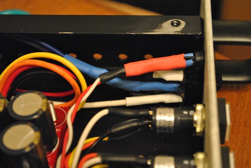
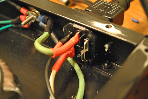
Top to Bottom: Red = LED, White = No Connection, Blue = blue/violet, White = Connection to fused IEC

6662986093_5e4f02b07f.jpg

Black = brown/grey, White = Connection to Switch

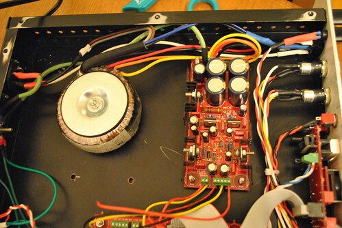
6662992717_85e5ab9e84.jpg

Updated overhead view after new wiring.

To be sure it wasn't the lacquer, I've re-stripped the wire ends that connect to the power supply and re-soldered all other transformer connections. Fuse is good. Still getting no voltage past the transformer.
 
I seem to have my wires from the transformer connected to the power supply in reverse order compared to Wave's wiring. I remember using a photo of another USA build using the same transformer to make that decision.

Could this be the problem?
 
drjoe said:
I seem to have my wires from the transformer connected to the power supply in reverse order compared to Wave's wiring. I remember using a photo of another USA build using the same transformer to make that decision.

Could this be the problem?
No problem here.
Your problem seems to be at primary side of your transformer and until you fix this you won't change a thing.
Wires colour coding and your visible connections matches the parts datasheets and last page from Mikes SB4000_ASSY_DOC_REV1. You already confirmed, your fuse is OK by ohming it out. Only other things left are your wires connections to the female disconnects (you removed the wire isolation in the crimp area?), your wire connections below your isolations (black->gray+brown), (blue+violet->switch pole), the maybe broken rocker mains switch (assumed SPDT mouser#611-D501001) and more unlikely both of your transformers primary windings. I'd start by rechecking for a conducting solid connection between wires and the female disconnects.
 
Harpo said:
drjoe said:
I seem to have my wires from the transformer connected to the power supply in reverse order compared to Wave's wiring. I remember using a photo of another USA build using the same transformer to make that decision.

Could this be the problem?
No problem here.
Your problem seems to be at primary side of your transformer and until you fix this you won't change a thing.
Wires colour coding and your visible connections matches the parts datasheets and last page from Mikes SB4000_ASSY_DOC_REV1. You already confirmed, your fuse is OK by ohming it out. Only other things left are your wires connections to the female disconnects (you removed the wire isolation in the crimp area?), your wire connections below your isolations (black->gray+brown), (blue+violet->switch pole), the maybe broken rocker mains switch (assumed SPDT mouser#611-D501001) and more unlikely both of your transformers primary windings. I'd start by rechecking for a conducting solid connection between wires and the female disconnects.

Thanks for taking the time to help me out.

To rule out a bad connection to the crimp terminals I pulled each color out one by one, turned the power on, and tested for voltage. Nothing on black, red, orange, or yellow.

Since yesterday I've completely reconnected black->gray/brown and blue/violet->switch. I'll rip the heatshrink off and check my work. If I get a solid beep between a bare part of the pole and a bare part of the wire, the connection is good?

The switch (indeed SPDT mouser#611-D501001) checks for continuity (bottom two poles beep when switch is on, top two beep when switch is off).
 
probably jumping the gun here, but you dont have those wire sticking out of the side of the PS when youre testing this thing i hope...  should remove the wires FROM the PS and leave em connected to the main board.  If one of those wires hits the chassis or something, not nice things can happen.

Also, make sure those heat sinks aren't touching each other & make sure you got the red orange yellow and black wires in the right terminals on the PS board. (measure voltage there too just in case one of them is not making contact.  (ive had a lead that was being held in place by the insulation... wire was never making contact with the terminal screw.)
 
drjoe said:
Yes and Yes. Getting 122VAC and my switch is oriented correctly.

So if you probe the neutral at the IEC (where the black wire tied to the brown/gray is soldered) and the bottom pole of your switch (where the white wire from your IEC is soldered) do you still get 122 VAC?
 
sr1200 said:
probably jumping the gun here, but you dont have those wire sticking out of the side of the PS when youre testing this thing i hope...  should remove the wires FROM the PS and leave em connected to the main board.  If one of those wires hits the chassis or something, not nice things can happen.

Also, make sure those heat sinks aren't touching each other & make sure you got the red orange yellow and black wires in the right terminals on the PS board. (measure voltage there too just in case one of them is not making contact.  (ive had a lead that was being held in place by the insulation... wire was never making contact with the terminal screw.)

I agree.
In your photo it looks as if you took the wires that go from the power supply board to the main board out of the main board. If there's voltage present at some point in this troubleshooting at those wire ends and they short out to the chassis, it could be dicey. You should remove them from the power supply board and leave them hooked up to the main board.
 
It's Alive! I went through everything we've covered one more time (replaced the fuse, re-soldered the transformer leads). I turned it on and measured the 20VAC at the transformer connections. Then I connected the main board and got the following voltages:

-15.02
-12.02
0.0
12.0
15.22

That's what I'm talkin' about!

I think it was the fuse after all. Boy is this thing brighter in person!

I can't thank you guys enough for all the help!

 
Back
Top