SB4000 Support Thread

GroupDIY Audio Forum

Help Support GroupDIY Audio Forum:

This site may earn a commission from merchant affiliate links, including eBay, Amazon, and others.
hey guys,
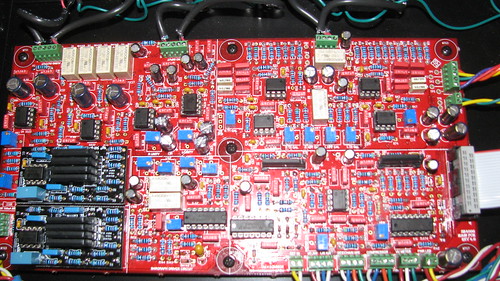
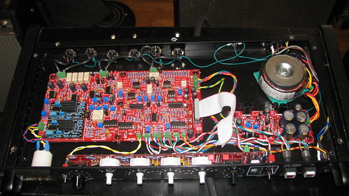
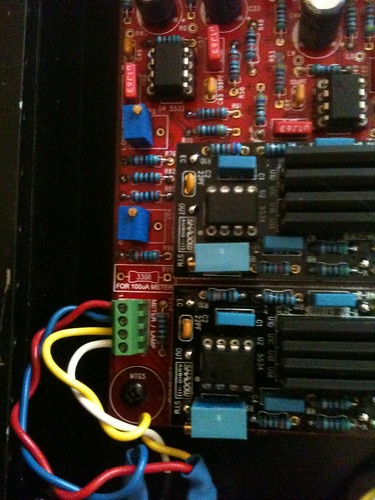
got my boards pretty much stuffed, got my case from par-metal. almost ready to start final assembly. quick question about the quad-vca boards...how exactly are these supposed to mount to the main PCB? From pics of other quad VCAs i see a pin/socket design to plug and play. does anyone have a p/n on the sockets/pins? i searched for 'mill-max', 'pins', 'sockets', etc. and couldn't find anything. thanks!

BD
 
Sorry for my absense of late, I was abducted by aliens.......no joke.....

sr1200 said:
You can get em from whistlerock audio or classic api. I think the two are a bit different.

Or you can just use some diode legs.  Breakaway male headers work fine as well, just break them into single pins, the body of the header works nice as a spacer so the VCA board doesn't short to anything on the main board.
 
drjoe said:
I removed the VCAs once again, jumped pin 1 to pin 8 on each VCA, and fired it back up with a 1k tone. When I engage the compressor, my right channel jumps 15dB on my DAW meter (I'm using PAZ Frequency). The left channel remains the same.
Got your probably wrong resistor value fixed ?
Your fault condition with audio-VCAs (not sidechain-VCAs) bypassed indicates, there is something wrong in your audio path.
(Why can't you just measure voltages ? A dBwhatever reading without reference doesn't make any sense and a 15dB jump from whatever voltage might just be a supply rail or A/D limit that might read 32dB or any other number with more headroom.)
Wild guessing, your supposed 15K R38 might be a 1M2 read backwards. There are some other possibilities to get it wrong.

With your 0dBwhateverreference signal feed from your D/A converter, measure the AC voltage across XLR pins2/3 at the cable end that plugs into your unit. Write your reference voltage down.
Bypass your pulled out audio-VCAs by linking pins1/8 with a piece of wire and power on your SB4000.
Now plug your XLR cables into your SB4000 input and measure voltage at U3-pin6 and U5-pin6. Should read the same as your 1st XLR cable reading, case not double check your 22K resistor values around U3 and U5.
With trimmers VR1 and VR2 dialed in for 30K, measure voltage at U4-pin1 and U8-pin1. Should be half of your previous reading, case not double check for 15K resistor values around U4 and U8.
Measure voltage at U4-pin7 and U8-pin7. Should be same voltage (but inverted polarity) as U4-pin1 and U8-pin1, case not double check your 10K resistor values around U4 and U8.
Good luck
 
for mounting pins on the quad vca boards...

i had a spare gar 2520 op amp kit around so i tried to fit the pins in the quad vca board mounting holes. looks like a 0.04" diameter pin is a bit too large, but i have some .032" diameter solder that fits through the hole. here is a part# for a pin that requires a .035" mounting hole diameter. it's backordered right now, but will be available soon. hopefully it will fit.

http://www.mouser.com/ProductDetail/Mill-Max/3117-2-00-21-00-00-08-0/?qs=sGAEpiMZZMsUzhEcHltCueJEqug8vjJN

anyone have a .035" allen wrench, solder, or other gauge they can use to test the diameter of the mounting holes on the quad VCA PCB?
 
Harpo said:
drjoe said:
I removed the VCAs once again, jumped pin 1 to pin 8 on each VCA, and fired it back up with a 1k tone. When I engage the compressor, my right channel jumps 15dB on my DAW meter (I'm using PAZ Frequency). The left channel remains the same.
Got your probably wrong resistor value fixed ?
Your fault condition with audio-VCAs (not sidechain-VCAs) bypassed indicates, there is something wrong in your audio path.
(Why can't you just measure voltages ? A dBwhatever reading without reference doesn't make any sense and a 15dB jump from whatever voltage might just be a supply rail or A/D limit that might read 32dB or any other number with more headroom.)
Wild guessing, your supposed 15K R38 might be a 1M2 read backwards. There are some other possibilities to get it wrong.

With your 0dBwhateverreference signal feed from your D/A converter, measure the AC voltage across XLR pins2/3 at the cable end that plugs into your unit. Write your reference voltage down.
Bypass your pulled out audio-VCAs by linking pins1/8 with a piece of wire and power on your SB4000.
Now plug your XLR cables into your SB4000 input and measure voltage at U3-pin6 and U5-pin6. Should read the same as your 1st XLR cable reading, case not double check your 22K resistor values around U3 and U5.
With trimmers VR1 and VR2 dialed in for 30K, measure voltage at U4-pin1 and U8-pin1. Should be half of your previous reading, case not double check for 15K resistor values around U4 and U8.
Measure voltage at U4-pin7 and U8-pin7. Should be same voltage (but inverted polarity) as U4-pin1 and U8-pin1, case not double check your 10K resistor values around U4 and U8.
Good luck

You were right! I had a 100k resistor in R48. Replaced it with the proper 10k and now the L/R problem is fixed.

Still having trouble figuring out my noisy compression. I wired up some breakout cables for the external side chain and I'm getting the same noise when the compression is triggered externally. Also, when feeding music into the sidechain, I can hear the music bleeding into the 1k test tone signal. Lots of weird modulations to the signal when adjusting the threshold..

Does any of this sound like a bad TL072? I remember quickly shorting out that chip earlier in my testing when I slipped off one of the pins.
 
hey guys,
I ordered some pins and sockets for the quad vca. will report back if they fit. for anyone using the par-metal case, here is a guide i made in Word using the ruler feature. Print this out and then tape it on the back panel, X marks the spot to make your punches so you can start drilling holes big enough for a 11/16" XLR size greenlee hole punch. Hope this helps somebody.


https://docs.google.com/document/d/1PbSyV4UqcOFRD5V0gClGTE3xANWQzrnRcl2NmBa2mEo/edit

BD

 
band_master said:
hey guys,
I ordered some pins and sockets for the quad vca. will report back if they fit. for anyone using the par-metal case, here is a guide i made in Word using the ruler feature. Print this out and then tape it on the back panel, X marks the spot to make your punches so you can start drilling holes big enough for a 11/16" XLR size greenlee hole punch. Hope this helps somebody.


https://docs.google.com/document/d/1PbSyV4UqcOFRD5V0gClGTE3xANWQzrnRcl2NmBa2mEo/edit

BD
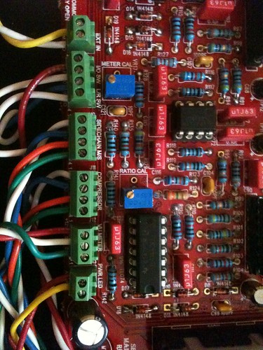
I'm sure it will help. One of the hardest things I had to do in this build was machine the par-metal case. I didn't buy a punch so I had to use a stepped bit. Lesson learned...buy punch. Other challenges were the power entry module and the stiffening lips.

Dave
 
for the IEC hole I started with an XLR sized punch and then taped off the rectangle size I needed to cut around it. then make center punch guides in the corners of your rectangle, drill some starter holes, and then use a dremel with a cutting wheel to connect the dots.

I haven't cut out the stiffening lip yet, but seems like another Dremel job.
 
Hi !

I finish my sb4000 build since couples of mounts ( all stock) but now i have a pair of dbx202c ( gold )  , and now i'm little confused in the installation someone can please advice me ?

i only need to remove all components under the vca's ,  put the two jumpers on JMP8/JMP9  and trim the vr1 /vr2 to 5k ??

or i need change any other component ?

Thanks !
 
hey guys,
here are the part numbers for the pins/sockets that go with the quad VCA boards from ruckus...fits like a glove!!!

http://www.mouser.com/Search/ProductDetail.aspx?R=0326-2-19-01-06-27-10-0virtualkey57510000virtualkey575-032620

http://www.mouser.com/Search/ProductDetail.aspx?R=3117-2-00-21-00-00-08-0virtualkey57510000virtualkey575-311720

cheers,
BD
 
just to be sure : for the Quad VCA board.
No components in the two rectangles labelled "left VCA" and "Right VCA" only two jumper JMP8 and JMP9 on the backside of the board ?
What is the function of VR1 on the quad vca board and how to calibrate it ?
thank you
 
hey guys,
google docs was messing with the format of my earlier post. here are some new links to download grids to make the mounting holes in the chassis...

Main PCB

https://docs.google.com/open?id=0B_CYf0EIc5E5MDZ6VHNGdDlUak84YTVYZS1mdHZGQQ

PSU PCB

https://docs.google.com/open?id=0B_CYf0EIc5E5X3EyLTFSdURRa3FQWkZzT1FSRjAyQQ

back panel XLRs

https://docs.google.com/open?id=0B_CYf0EIc5E5RWR5azFMd3NTRzZMV0MyR29oYU5IQQ

cheers,
BD
 
Not far off now..

Ubyglq0L
 
lowtone said:
just to be sure : for the Quad VCA board.
No components in the two rectangles labelled "left VCA" and "Right VCA" only two jumper JMP8 and JMP9 on the backside of the board ?
What is the function of VR1 on the quad vca board and how to calibrate it ?
thank you

Changes required to the main board is indicated on the Quad VCA BOM at beginning of this thread.  There are some additional component changes in addition to what you indicated.

50K Pots on Quad boards are for trimming THD.  Instructions are in the first post of this thread.
 
Hi,

After some work related break, I am getting back to debugging my build
Went over all component values as del las looked for build defects. So far it seems ok.

Have jumpered the two VCAs pin 1 with 8 in order to get a clean signal. Got it.
Then placed back the 2181As and jumpered the 2181C. Compression was at around -12db and got the same distorted signal from outputs. It looks like it is a function of the compression ratio, even when the input and output signal levels are relatively low to not cause audio distortion.

Have inserted a completely new batch of 2181A and 2181C, but same results.

Perhaps there is a list of expected voltages on ICs pins for me to compare?

Strangely, when testing continuity, I got positive on the power supply between -15 and -12 to ground. Is that ok? This only happens when the unit is powered and after shutdown, the continuity stop when the power caps are emptied.

I am puzzled. After good hours I can safely say that I do not have any new ideas.
 
Hi guys,

I have put together a SB4000 to use on some mixes here... top quality project, tons of options and very well documented. Hats off!
It took me a day to assembly and another day to metal things and finish it. It worked 99% from the first power on! :)

All controls act perfect and doing what they suposed to do... bypass, external in, att, rel, makeup, VU reads fine, calibrates well... BUT threshold. It doesn't change a thing. It varies the DC between +12 and -12 going to U13 but have no effect on the compression (from none to full). Have cross checked between GSSL, Alan Smart C1, SSL original schemos to look for small differences, and all seems fine and correct. Have changed all ICs just in case, all the same. Have checked every resistor since I did it so fast but all looks fine too! Had R169 (47k) in AND jumped and all nothing changes.

The only thing different is I'm using dbx u1252 as VCAs, sort of THAT 2150(THAT 2159 actually) so I've changed some resistor for THD trimming as THAT recommed for it, and all the rest is stock.
Also left led VU out, so this portion on board is not populated.

Totally clueless of this ghosty bug at this point, but still looking :)
Have looked all this thread and seems that no one had a similar issue. Have done 3 ou 4 GSSL for friends in the past and no problem too, and the values for sidechain and all are very alike!

Any suggestions? Anyone had a similar issue and fixed without posting here?

many cheers!
Fabio


Never mind, just found the issue!

Never saw something like this before, a resistor that was open (!!!), looked perfect outside, no burn, nothing, but played open in the threshold circuit. Crazy!!

Now it's perfect!

cheers,
Fabio
 
ok, i redid my unity gain settings using a 1Khz sine wave at -10db with threshold fully clockwise and gain set to zero. had to make sure both input and output were set for +4dBu in my DAW. I am now getting the same input and output levels when the unit is in bypass and when it is engaged. still stuck on step 3...my voltages at TP8 and TP10 are 2.9v while  max voltage at TP11/TP12 is 1.4v? I trimmed VR11, VR12, VR13, VR14 to spec according to the BOM.

Any ideas? are those the correct front panel settings for unity gain calibration?

BD

6823951312_a251af861b.jpg

6970071405_1566a85a45.jpg

6974146969_fb0aba7751.jpg

6974145867_e2eda9f7d1.jpg


Latest posts

Back
Top