You are using an out of date browser. It may not display this or other websites correctly.
You should upgrade or use an alternative browser.
You should upgrade or use an alternative browser.
sontec 1 RU build thread
- Thread starter dagoose
- Start date
Help Support GroupDIY Audio Forum:
This site may earn a commission from merchant affiliate
links, including eBay, Amazon, and others.
After weeks of starring at my non-working I/O PCB i finally figured out that I stuffed 2604 istead of 604... 
Now my first one works wonderful. :guinness: to Igor for this project.
Now my first one works wonderful. :guinness: to Igor for this project.
khstudio
Well-known member
Speaking of 604's... They're about impossible to find in the US at this point. 
Mouser & Digikey both are sold out with ridiculous wait times that arent even guaranteed.
So... for now, I'm just going to use a JLM HYBRID on the inputs (with the servo disengaged - because there's a servo already on Igor's PCB)
& the JLM 99v's for outs.
I too wanted to just get 604's for the inputs... oh well. :sad:
Hey... do any of you guy have 2 spare 604's you can sell & send me :?:
I'm in the US.
Thanks,
Kevin
PM sent...
crisotop
Well-known member
Found my problem - had a bad solder joint on the 6/12dB slope switch - now both channels match perfectly, many thanks for the effort igor and the rest of the forum for your help!
happy eqing
Christoph
happy eqing
Christoph
Hello Igor (and other Sontec builders): Are the equations for calculating the filter boost/cut gain and frequencies available somewhere? I would like to build the EQ with 24 step switches for frequency select and boost/cut. Perhaps 6 or 12 step switches for slope. Many thanks.
Best,
James
Best,
James
khstudio
Well-known member
Igor,
I don't really know much about the Sontec (or ITT) EQ's except my friend has a Sontec MEP250a & told me all about it & how much he loves it...
which is one of the reasons I got your kit.
OK, he sent me a schematic for his MEP 250 (A)
I was checking over the filters & noticed none of the values match the ones in your clone.
Now, I know there are different revisions of this EQ BUT which Version is yours the closest to or derived from :?:
It's NOT a big deal & I'm not complaining... just trying to learn a little bit about what I have hear.
The other reason is I may want to make some changes to the circuit... actually the LOW SHELF. I may want to put it back to stock.
You mentioned changing it to a smother roll-off & I may prefer the SHARPER slope of the original.
Thanks IGOR, :thumb:
Kevin
BTW... I would have had it done yesterday but the case i bought has defective side panels & missing parts. :sad:
I'm going to steal some parts from another case until they replace them so I can finish it TODAY... Hopefully. :green:
dagoose
Well-known member
[quote author="jamesfei"]Hello Igor (and other Sontec builders): Are the equations for calculating the filter boost/cut gain and frequencies available somewhere? I would like to build the EQ with 24 step switches for frequency select and boost/cut. Perhaps 6 or 12 step switches for slope. Many thanks.
Best,
James[/quote]
would be nice indeed... i'm also thinking of 'modding' my sontec with stepped swithes since it's just more accurate for mastering, which i use it for.
Best,
James[/quote]
would be nice indeed... i'm also thinking of 'modding' my sontec with stepped swithes since it's just more accurate for mastering, which i use it for.
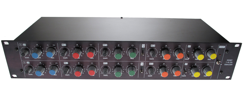
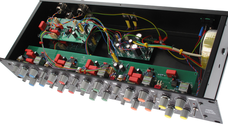
Here's my finished EQ. Thanks to Igor and Tat for this project, it sounds wonderful. I will build a second unit.


Purusha
Well-known member
Wow, these photos look really good 
Good job! 8)
BTW, where did you get those knobs?
Good job! 8)
BTW, where did you get those knobs?
Tat, the knobs are from Sifam, I purchased them from Sibalco.de
The article # is 3001768 for the 15mm and 3000195 for then 10mm knobs. Thanks for liking the photos ;D
The article # is 3001768 for the 15mm and 3000195 for then 10mm knobs. Thanks for liking the photos ;D
Purusha
Well-known member
Thanks. Do they take Paypal?
Tat, I assume not. Look at their website. IBAN is surely possible.
Purusha
Well-known member
Thanks!
khstudio
Well-known member
OK... I FINISHED MY SONTEC!!! ;D
It absolutely kicks ass & I LOVE it!!!!!!
BUT... It's also kicking the ass of my mixing consoles insert returns.
WHY... because there's 3+ VOLTS OF DC coming out of the unit!!!!!!!!!!!!
My faders are scratchy. This NEVER, EVER happened before...
So, I put my meter on the output of the Sontec & there it was... 3+ VDC!
WHY?
What would cause this?
I have the servo installed!
I'm using JLM 99v's for the output.
PLEASE HELP... OR guide me on WHAT to check for to fix this.
(Note - I did have the output wiring messed up at first... I thought that pins 1, 2 & 3 on the XLR's would match the pins 1, 2 & 3 on the MOLEX connector : "Standard stuff" NO??? Well...Not on this unit. I was having strange issues on the first fire-up, then finally looked at the schematic & sure enough... they were wrong, so I fixed it.)
I had Pins 2 (HOT) & 1 (GND) swapped!!!
Could that wiring mistake somehow "Damage" the Servo??????
It absolutely kicks ass & I LOVE it!!!!!!
BUT... It's also kicking the ass of my mixing consoles insert returns.
WHY... because there's 3+ VOLTS OF DC coming out of the unit!!!!!!!!!!!!
My faders are scratchy. This NEVER, EVER happened before...
So, I put my meter on the output of the Sontec & there it was... 3+ VDC!
WHY?
What would cause this?
I have the servo installed!
I'm using JLM 99v's for the output.
PLEASE HELP... OR guide me on WHAT to check for to fix this.
(Note - I did have the output wiring messed up at first... I thought that pins 1, 2 & 3 on the XLR's would match the pins 1, 2 & 3 on the MOLEX connector :
I had Pins 2 (HOT) & 1 (GND) swapped!!!
Could that wiring mistake somehow "Damage" the Servo??????
khstudio
Well-known member
NEW INFO:::
I just tried installing NEW 2604's & it didn't help.
Also, ALL this testing & DC was found when I use the unit Un-Ballanced!
(grounding pins 1 & 3 on my patch bay - using 1/4 in, tip, ring plug)
I haven't tested for DC in Balanced I/O yet... but that shouldn't make a difference.
I also don't have the 150p (c59) installed!!!
Should I? I thought it was for stability but I could be wrong.
My original plan was to use 604's first... which is why I didn't install c59.
I guess I should put them in???
Thanks
khstudio
Well-known member
OK...
I tried using the JLM Hybrid op-amp in BOTH the input & output positions &
... either the Hybrid doesn't have as much DC offset spitting out of it or the circuit (as designed) doesn't
work on removing the DC from the JLM 99v???
This doesn't make sense.
I tried using the JLM Hybrid op-amp in BOTH the input & output positions &
... either the Hybrid doesn't have as much DC offset spitting out of it or the circuit (as designed) doesn't
work on removing the DC from the JLM 99v???
This doesn't make sense.
khstudio
Well-known member
EMAIL ABOUT SERVO & JLM 99v's
To Joe:
FROM Joe:
To Joe:
Hi Joe,
I'm using your 99v for the output of my SONTEC EQ.
The PCB has a Servo but it doesn't seem to be working right.
Could you PLEASE check out the schematic (posted below or attached) to see
if there's any problems or changes that should be made to work properly???
I'm getting over 3 Volts of DC, with the Servo hooked up!!!
I've tried a few things, like changing out the 2604's but nothing is
helping.
Thank You,
Kevin
FROM Joe:
HI Kevin
With a 10k and 100R you would need to have the servo output go to
about -100v to remove the DC offset the way the circuit is. This is fine for
normal opamps with only small mV offsets but will not work on the 99v.
Remove R11 100R and it should work fine with the 99v. You could fit a 2u2
Bipolar cap or larger in thr R11 position instead to give a smoother DC
Servo with less noise from the servo opamp.
Let me know how you go
Thanks
Joe Malone
JLM AUDIO
Similar threads
- Replies
- 192
- Views
- 80K
- Replies
- 205
- Views
- 67K
- Replies
- 14
- Views
- 6K
- Replies
- 183
- Views
- 74K


