Soundcraft 500/600 measurement and improve

GroupDIY Audio Forum

Help Support GroupDIY Audio Forum:

This site may earn a commission from merchant affiliate links, including eBay, Amazon, and others.

xarolium

Well-known member
Joined
Feb 5, 2007
Messages
98
Dear Diyer,

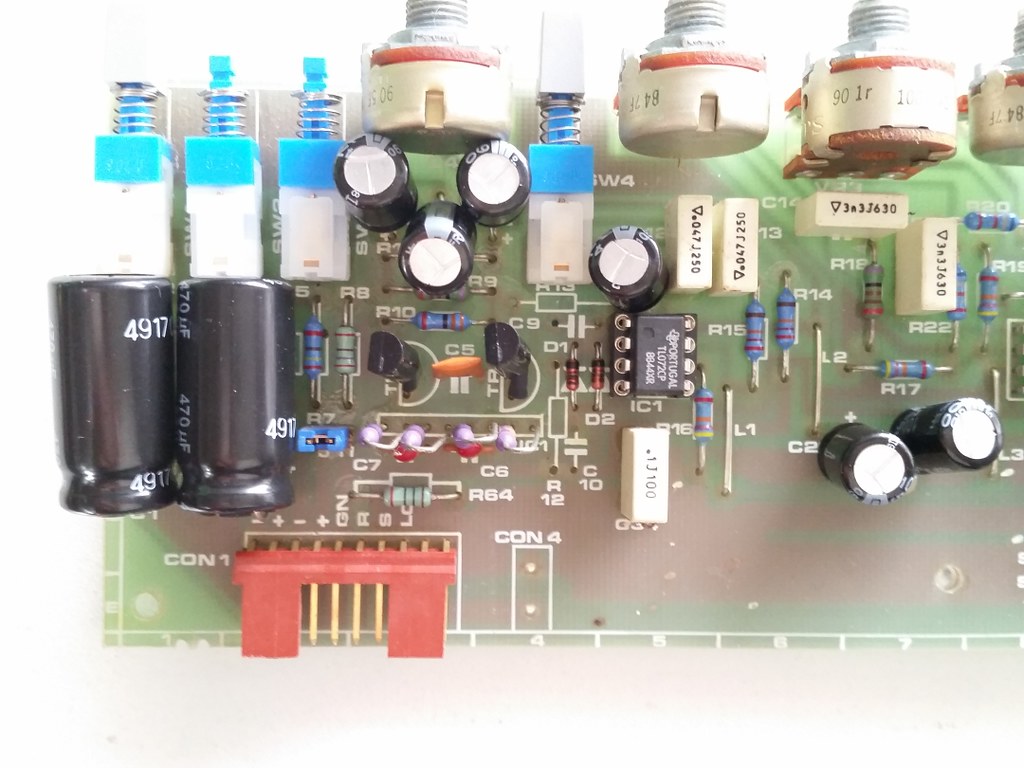
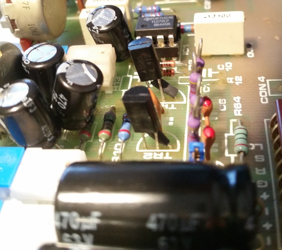
After more than one year spend to recapping / cleaning / fixing my soundcraft 600 i'm now spending time to measure to improve a little bit the board.
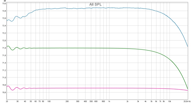
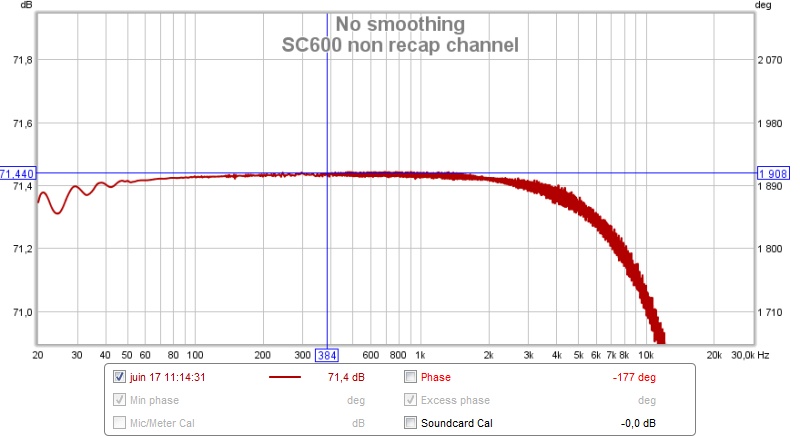
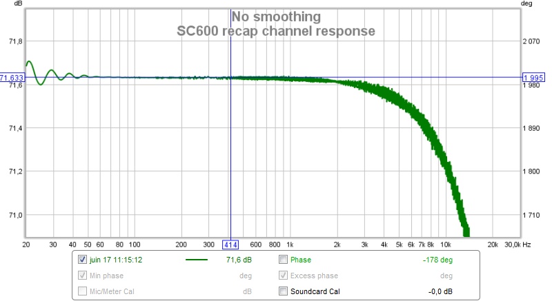
First thing here is the frequency response of a recap and a non recap channel. Bottom end are lot better but no difference at the top end:
27723729115_2e0a652e19_c.jpg

27689806566_a8df95be55_c.jpg


How can i improve top end response ?

So second thing is about THD. I first measure a huge total harmonic distortion and i was a little angry of it  :eek: more than 0.5ù of THD is too much!!
27111250634_184e773387_c.jpg


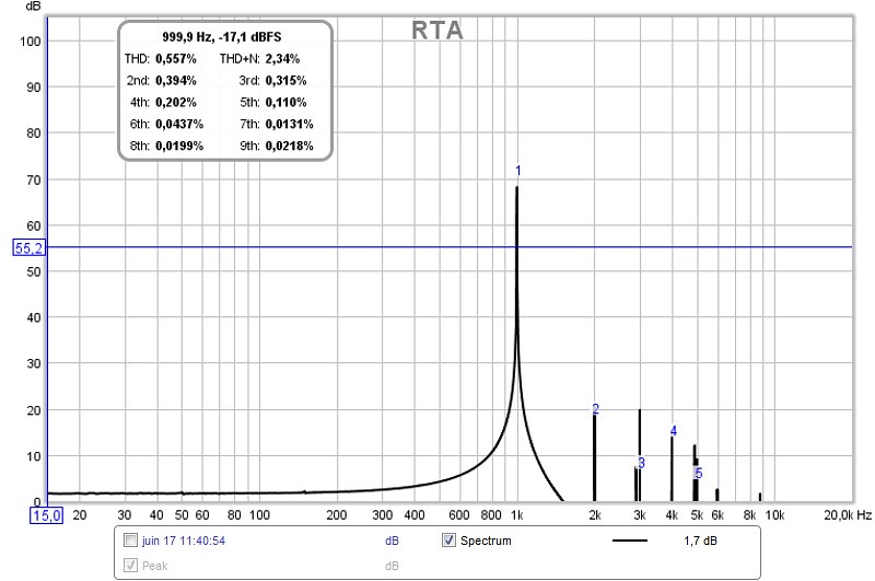
Then i start moving masters level like OSC level and what's a surprise THD get lower when OSC level is not to 0:
27623146432_6a6a511fb8_c.jpg


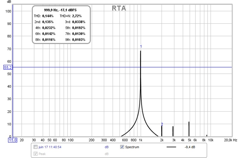
But 0.144% THD is not acceptable too so i unscrew the master channel to check solder on PCB and everything and at the moment when Master channel faceplate was isolated from the chassis ground THD became  normal =>0.04%. Is not so bad
27113159663_594547ae5b_c.jpg

27445646660_7f8014dfa1_c.jpg


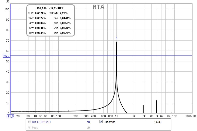
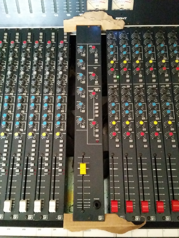
My question is how to solve this ground issue i can not keep my master channel on piece of paper like that !! And why moving OSC level change THD level ?!!

Thank you for your help
 
diko2 said:
Hi,

I'm not sure to understand your THD measurement setup.
Do you use internal generator or external one?

Morgan

I use RWE software to measure and generate 1KHz sine wave
 
Some tips when using REW.

1. You need to calibrate your sound card first. REW can then compensate for its frequency response. It is not clear if the response you have measured is of the Soundcraft alone.

2. Change the limits on your frequency rsponse plots so you can see the actual level at 20KHz.

3. When using the RTA function to see spectra and distortion, always use the dBFS scale - that's the only way you can be sure you are not overloading your soundcard input.  which will definitely cause incorrect distortion measurements.

Cheers

Ian
 
ruffrecords said:
Some tips when using REW.

1. You need to calibrate your sound card first. REW can then compensate for its frequency response. It is not clear if the response you have measured is of the Soundcraft alone.

2. Change the limits on your frequency rsponse plots so you can see the actual level at 20KHz.

3. When using the RTA function to see spectra and distortion, always use the dBFS scale - that's the only way you can be sure you are not overloading your soundcard input.  which will definitely cause incorrect distortion measurements.

Cheers

Ian

1. Done ;)
2. Done too
3. And done !

Thank you for your advices.

After some sound check i fixed the issue. The problem came from JFET transistor used to switch between Mix L/R and PFL busses. Both TR11 and TR13 J112 transistor was faulty. I replace it with fresh new BF245A (that is the one i have in stock), changed D1 and D101 too and good bye THD  ;), No at all but now THD is around 0.03% 0dBvu 1Khz sine wave. Quite good but i know it could be better by improve master signal pass, summing transistor and OPA.

Do you know any tips i can do to improve S/N and THD ?


Check if the meter circuitry creates distortion, probably via ground pollution.

Line input uses the same circuit as the mic amp with a pad before it, it's not ideal. I never liked the sound of that servo, I eliminated it in my 200b (pretty much identical circuit, textbook Douglas Self, see his book "Small Signal Audio Design").
TL072/71 are used throughout the channels, NE5532 / NE5534 lower distortion and noise here. The post fader amp has to drive the master, auxes and channels, I got much improved performance using a DOA here. An OPA132/134 is also much better than the TL071 original used.

You might be able to improve performance by adding the usual local decoupling (10-100nf ceramic +  10uf electrolytic) to ground.

I've added input transformers and an API mixbuss to my console, more THD at low frequencies, but sounds great. ;-)

Top end response may be an artifact of your sound card. You can play with the feedback caps in the discrete input section to get better high end response. I changed all the feedback caps for NPO types, too, for lower distortion.
 
Xarolium, in the EQ section you better avoid 5534, use a FET input here (personally I think tl072 is fine).

Hey living sounds, what transformers did you put in front of the preamp? 1:1 or step-up (in a Balanced/Balanced configuration)?
I have a B100 btw. (small broadcast model with circuitry close to 200B), I like the sound, clean and punchy and I like the rather minimalistic signal path.
 
L´Andratté said:
Xarolium, in the EQ section you better avoid 5534, use a FET input here (personally I think tl072 is fine).

Hey living sounds, what transformers did you put in front of the preamp? 1:1 or step-up (in a Balanced/Balanced configuration)?
I have a B100 btw. (small broadcast model with circuitry close to 200B), I like the sound, clean and punchy and I like the rather minimalistic signal path.

Why would you avoid 5532/5534 in the EQ section? There is no problem with pots scratching, and noise and distortion ist lower than with the TL072. I tried too many op amps to count in there but ended up with the TI made 5532 version (by ear).

I put Beclere 3:1 step down line transformers on the inputs. These replace the voltage divider on the line input. I also changed the entire gain structure for pure line use.
 
Ah, ok, I was thinking about mic transformers...

living sounds said:
I tried too many op amps to count in there but ended up with the TI made 5532 version (by ear).
The input Z of the 5532 is as low as 100k  iirc, so will load down the r-c network (theoretically), but I won´t argue against your ears! :)
 
living sounds said:
Check if the meter circuitry creates distortion, probably via ground pollution.

That was exactly the problem i had. When i unplugged master meter from the master board, distortion gone.
How do you solve it ?
 
xarolium said:
That was exactly the problem i had. When i unplugged master meter from the master board, distortion gone.
How do you solve it ?

Unplugging master meter from the master board :D :D :D
Sorry, but i couldn't resist :D
 
I modded a channel to try to get better top end and it was a success.
Have a look on this measures:
Blue => Non recap channel  Green => recap channel    Pink => recap channel and Trans Amp mods
27664692982_5246e7f348_c.jpg


With the trans. amp mods the S/N is now 99dB instead of 97dB without the mods.
Here is the modded schematic. My PCBs are Issue 9 and normally it already should have this mod but not. Have a look on the right of the schematic you can read soundcraft issue mods. The issue 6 tell : Mic Amp cir add and C36. like i told you i have Issue 9 and i never find IC6 who was on the original schematic and all components around like C38 (a second 100/10 gain coupling cap in parallel of C8)
27691534081_390257523c_k.jpg

27731909066_eb323df11f_b.jpg

27665486502_98aa673c69_b.jpg

27691690291_f051df39a4_b.jpg

27691688861_c965d4d146_b.jpg


Like you can see on the picture i add local PSU decoupling 0.1uf ceramic capacitor to try different AOP. I tried a OPA2134 instead of the TL072 in the Amp section (IC1) and a LME49710 as a fader AOP. Noise was still the same and measure didn't change so i keep the original one at the moment.
I need to make sound by ear check to know if replacing AOP upgrade sound or if it's just a fantasm...  ;)

Next step replace the summing transistors by 2SA1085 in the master module
 
Usual i had better results with OPA 2134/2604 but you need to remember that OPA take double current than TL.
Count for each channel.
Also good practice with opa are 100nF caps from each supply pin to ground.
With opa as IC1A i would measure dc offset - there's probability, that this one cap after it could be jumpered.
You can even try to removed and the hpf switch will show is there dc offset :D
Be carefull with oversized capacitors. 470uF is really high value for most of the places here. Sometimes can dull the sound.
For ceramic caps i would suggest NP0/C0G type.
 
ln76d said:
Usual i had better results with OPA 2134/2604 but you need to remember that OPA take double current than TL.
Count for each channel.
Also good practice with opa are 100nF caps from each supply pin to ground.
With opa as IC1A i would measure dc offset - there's probability, that this one cap after it could be jumpered.
You can even try to removed and the hpf switch will show is there dc offset :D
Be carefull with oversized capacitors. 470uF is really high value for most of the places here. Sometimes can dull the sound.
For ceramic caps i would suggest NP0/C0G type.

I know that OPA use lot more current than TL072 but if i decide to use OPA i will take OPA1642 who is 1.8mA per channel as the TL072.
Like you can see on the picture i already add 100nF ceramic caps to decouple each power supply rail on the OPA.

What do you mean by "dull the sound" ? i do not ear any "strange" thing in the sound.


For now i tried this following AOP on IC1:
-JRC4558 = sound flat and close
-OPA2107 = sound a little more distorted than the TL072
-OPA2134 = Sound punchy, clear and clean
-OPA2137 = sound more punchy than the 2134 but not as clean
-NE5532 = sound quite the same as the TL072

 
L´Andratté said:
The input Z of the 5532 is as low as 100k  iirc, so will load down the r-c network
In most cases, the input impedance is bootstrapped by NFB to about 10-50 times more. It is quite possible to have an actual input impedance of several megohms with a 5534. Noise performance may not be adequate for a very large source impedance, though.
 
xarolium said:
I know that OPA use lot more current than TL072 but if i decide to use OPA i will take OPA1642 who is 1.8mA per channel as the TL072.

From the current consumption side is a good choice - give us know how it work in different matters. I didn't tried.

Like you can see on the picture i already add 100nF ceramic caps to decouple each power supply rail on the OPA.

Great! Sorry, i didn't check the pictures. Am in rush all the time so i only looked on the schematic ;)

What do you mean by "dull the sound" ? i do not ear any "strange" thing in the sound.

Dull is dull :D I don't know how to describe that better, but i had some strange behaviors of equipment when recapped for much higher values. All depends on circuit topology, impedances etc. Hmm... something like killing transients, low mid exposure,
blanket on the speaker :D :D :D
Best option is always comparison - if you didn't noticed anything wrong - that's great!
If the impedances will be higher i would go down with capacitance (in that way i didn't had any problems) and use foil caps.
You could try at some points - with 22k  - 4.7uF - 10uF range of foil cap should give you low end cut after 10Hz.
If there's option to take out cap - i will also try. Results are sometimes surprising - but all depends on the equipment - it's not general rule ;)
 
xarolium said:
Like you can see on the picture i already add 100nF ceramic caps to decouple each power supply rail on the OPA.
Rather than 100nF ceramics, you'd be better off using electrolytics.  They have to be AT the OPA, certainly closer than 1", and they need to decouple to a 'DIRTY GND' which isn't used for feedback or signal.

For now i tried this following AOP on IC1:
-JRC4558 = sound flat and close
-OPA2107 = sound a little more distorted than the TL072
-OPA2134 = Sound punchy, clear and clean
-OPA2137 = sound more punchy than the 2134 but not as clean
-NE5532 = sound quite the same as the TL072

If you want to try OPA rolling, have a look at Kingston's opamps and local decoupling of rails, some questions
http://www.groupdiy.com/index.php?topic=37307.80

Many true gurus chime in.  It proves how OPA rolling takes a VERY poor second place to correct earthing, layout & decoupling.  It’s a long thread but read the whole thing from #41 to find pearls of wisdom.
 
ricardo said:
It proves how OPA rolling takes a VERY poor second place to correct earthing, layout & decoupling. 
I would add that the performance differences between opamps depend very much in their tolerance regarding their environment.
Products that go beyond simple phono preamps or headphone amps in complexity (like mixers) suffer inevitably from compromises in layout, because there is not one single input orifice or single output orifice - add to that the monetary constraints that impose the presence of unbalanced connections.
Several über opamps perform up to expectations only in a very "protected" environment; when put in a real-world situation, they may have worse performance than some pedestrian opamps. I guess the perennity of TL0's and 5532/4 is due to that fact. I used a lot of RC4559 and MC330178 for that reason.
I think in the modern opamps OPA2134 is one that gives superior performance without being fussy about layout and decoupling.
At the opposite, it seems the LME49990, which is on paper the winner, gives hard times to designers when put in situation.
Quite often I see comments from audio tweakers criticizing manufacturers for their use of "inferior" opamps. Designers have a responsibility to design product that work reliably when they come out of a manufacturing chain, and indeed, cost is a factor. That justifies the use of non-fussy components.
 
How would I go about changing the voltage needed for a OPA2134 rather than TL072 in Soundcraft 600? Would this need to be a change in power supply? Buffer the OPA2134? change Resistors to give more current? Just decouple the opamp? a combination of all? something else? Any help appreciated.
 
I modded a channel to try to get better top end and it was a success.
...
With the trans. amp mods the S/N is now 99dB instead of 97dB without the mods.
Here is the modded schematic.

1638666479963.png

I see two potential problems with your "trans. amp mods". One is that driving the emitter mic+ transistor TR2 could easily mess with your CMRR which could equate to high frequency noise getting in. The other is that the larger coupling caps could pull enough current through the collector junctions of TR1 and TR2 to burn them out if someone plugs a line out into the mic in (AKA The 48-Volt Phantom Menace problem).
 
Back
Top