SSL "Talkback" Listen Compressor

GroupDIY Audio Forum

Help Support GroupDIY Audio Forum:

This site may earn a commission from merchant affiliate links, including eBay, Amazon, and others.
livingnote said:
Oh great :) What software are you working in?

I'm using NI Ultiboard 10 for the layout.


The other pot at the input opamp appears to be for gain. Seems like T3, which is a NE5534, amplifies and the pot beside T3 controls the feedback loop.  If you crank the input you would likely get more reduction from the FET i'd think?  Maybe that's the LESS/MORE control? But I wonder if you'd get a hotter signal at the output then?   I dunno, it looks to me T3 is for gain input, but maybe it means more compression too....

Guess I'll just have to try it out ;)

(Schematic - http://www.nrgrecording.de/temporary/talkback_limiter.pdf)
 
Guys, The less/more in the SSL plug-in is going to do the same thing as a crush-&-blend.

Build the basic circuit and wrap it inside a crush-&-blend. -You should find that you'll have the same functionality as the plug-in.

The original console compressor is just a HARD-LIMIT, with no control over ratio. Adding a crush-&-blend to it will allow you to still maintain the effectively infinite limit ratio, but still control HOW MUCH the signal gets mashed... -Just like the plug-in.
Trust yerevverluvvin uncle Keef.

Crush-&-Blend ROCKS. SSL compressors ROCK.

Put 'em together and you got Rock-in-a-box, with knobs on.

Keith
 
SSLtech said:
Guys, The less/more in the SSL plug-in is going to do the same thing as a crush-&-blend.

Build the basic circuit and wrap it inside a crush-&-blend. -You should find that you'll have the same functionality as the plug-in.

The original console compressor is just a HARD-LIMIT, with no control over ratio. Adding a crush-&-blend to it will allow you to still maintain the effectively infinite limit ratio, but still control HOW MUCH the signal gets mashed... -Just like the plug-in.

Thanks for the info Keith!  I haven't taken a look at the crush & blend circuit yet. If its not to much hassle to add then i could probably do it.  I have a layout for the talkback circuit. basically copied what the card has.  so crush and blend would be sorta like adding a wet/dry then?
 
One word of advice - set your layout up and then keep the resistors in the middle divider section as well as the feedback R across the OPA socketed and interchangeable - I spent a lot of time fudging with those till I got it right.
 
If you've got an 8 pin dip socket or likewise, just cut it into individual sockets with a dremel...
should work very handy

cheers,
dave
 
Exactly. Or just your side cutters, does less damage. It's a bit finger-burning territory if you don't have the right equipment, so be quick when you solder ;)
 
...Or even better...

Just use the DIP socket as-is (without modification) and route ALL the resistances which you might wish to 'adjust' through "pin-pairs"...

For example, using a 16-pin DIP socket:
Resistor 'A' between pins 1 and 16
Resistor 'B' between pins 2 and 15
Resistor 'C' between pins 3 and 14
Resistor 'D' between pins 4 and 13
Resistor 'E' between pins 5 and 12
Resistor 'F' between pins 6 and 11
Resistor 'G' between pins 7 and 10
Resistor 'H' between pins 8 and 9

Does that make any sense?

Keith
 
Ooooh now that rocks :)

Especially in the case of CnB I know for a fact this is easy to do, very much within the nature of the layout.

I know what I'm doing next time...
 
Right on, yeah i figured, but i'd never tried it and wasnt sure if the resistors would fit in the sockets! cool

So I'd like to take the clean side of the crush-n-blend right after the input opamp (T3 on the nrgrecording schemo) so that i'm blending the amplified clean signal with the amplified then compressed side of the signal.  Is the SSM2141 used just to go from a balanced line? Could I just eliminate it and go straight from the signal after T3?

...clear as mud? maybe i should post a schemo of what im talkin bout?

 
No, not at all, you're running into the same issue why I designed the internal crush to begin with. The SSM is indeed to recieve bal signals and I just ultimately dropped it to go straight into the SSL's signal path - so you have two options here:

Keef's schemo is basically an entire bal I/O section with CnB functionality - what he had in mind when he made it was to build a separate box that is highly versatile in that you can use it with any device by patching. For installing into the in / out line of a device that already has bal I/O you just need a coupla buffers and a pot like I did here (quoted from the CnB thread):

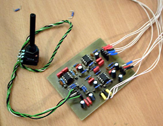
intcrush.jpg


Here is the schematic

I decided to go with the 4:1 ratio but now looking at it and (if I got this
right) by the output opamp's input being at ground, we end up with the
pot in parallel (?) with r2, r4 etc and thus get around 8:1, changed
the output feedback r to 91K and now gain is unity to exactly .1 dB.

If you want to etch & build it, here you go:

Components

Photopositive 1200 dpi

And just for Kicks, I did a little crossfade test:

Bing&Dimmu


Hope that helps you get sorted. The other option would be to make a half-baked one, with SSM bal receivers on the input which feed T3 and provide at the same time the dry line into the CnB potted divider (nice buffering all around) and just a 5532 for the wet line (stick your talkback output in there), and then using the other SSM as the general bal output.

Make sense?
 
Yeah makes sense sorta.  Could I do something like this?? I don't see why not, but that's why I'm asking haha


Attachments

  • Talk-N-Blend.gif
    Talk-N-Blend.gif
    96.6 KB · Views: 222
Won't work. U6 pins 2 and 3 are seeing the same signal. U6 will only amplify the DIFFERENCE.

Replace U6 with unity gain inverter and you'll have more luck.

Keith
 
Ah i seee... Something like this then with a 5532 instead? :

Not really sure how to implement this..


Attachments

  • Talk-N-Blend_2.gif
    Talk-N-Blend_2.gif
    97.8 KB · Views: 148
Back
Top