I've been through that mill. No need for you to have to go there too.
But if you want to know the way there - here goes:
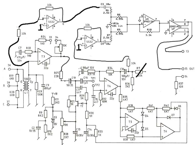
The potted divider is a divider made up of two resistors - and their ratio determines the output voltage - R1/R2.
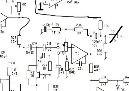
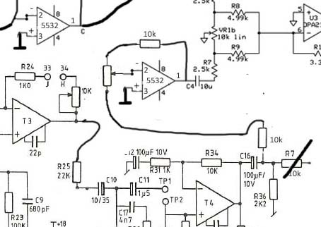
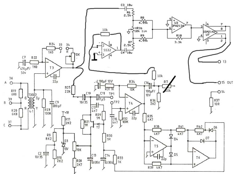
[Edit here these are R6/VR1b and R7/VR1b in your schemo]
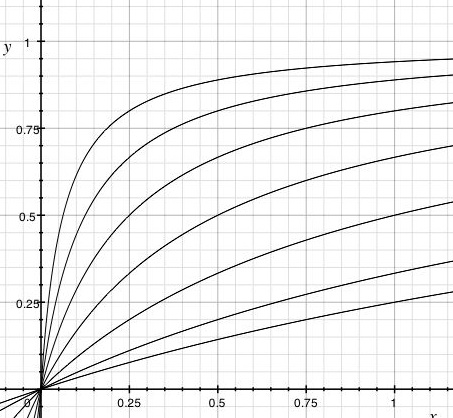
Depending on the value of R1 (the one that isn't the pot) you'll get different voltage behaviors when you twiddle
the pot. In the setup above, you will get a sharp climb the first quarter turn and a very shallow climb thereafter-
not much feel to that. So here I plotted out some curves for varying R1's:
The higher R1, the flatter the curve, which is yay because you're getting closer to linearity that way. Of course,
the higher the resistance of R1 is, the more impressed the electrons will be by R1 and the more voltage will drop there,
so the less voltage will drop across the pot in turn, which means you need to fudge the OPA's feedback to deliver more bang in order to restore more or less a unity output.
You can save yourself the entire merry-go-round by simply using the R values specified in my schematic for the CnB, they work and imho they feel right.


")


![Soldering Iron Kit, 120W LED Digital Advanced Solder Iron Soldering Gun kit, 110V Welding Tools, Smart Temperature Control [356℉-932℉], Extra 5pcs Tips, Auto Sleep, Temp Calibration, Orange](https://m.media-amazon.com/images/I/51sFKu9SdeL._SL500_.jpg)