You are using an out of date browser. It may not display this or other websites correctly.
You should upgrade or use an alternative browser.
You should upgrade or use an alternative browser.
The official GroupDIY 511 Help & Support Thread
- Thread starter [silent:arts]
- Start date


Help Support GroupDIY Audio Forum:
This site may earn a commission from merchant affiliate
links, including eBay, Amazon, and others.
kato
Well-known member
unlikekurt said:Are these simply "metalwork isn't perfect" things or should I be doing something to relieve this?
I'd say a few taps with a hammer and you're back in business.
Winetree
Well-known member
Had the same problem. Took care of it with a rubber mallet.
It won't harm the finish.
It won't harm the finish.
New Soul Rebel
Well-known member
- Joined
- Mar 25, 2010
- Messages
- 135
This is a noob question, my apologies.
what are all the jumpers/headers actually for? If I don't want stereo channels etc, do I need to install them?
I plan to install ALL single channels as this will be a front end of pres only.
Matt
what are all the jumpers/headers actually for? If I don't want stereo channels etc, do I need to install them?
I plan to install ALL single channels as this will be a front end of pres only.
Matt
[silent:arts]
Well-known member
Hi Mat,
leave the stereo jumpers out, no problem.
for the XLRs, I would hardwirwe pin1 to chassis.
(depending on the used modules, if there are any problems, you are more flexible with the jumpers)
leave the stereo jumpers out, no problem.
for the XLRs, I would hardwirwe pin1 to chassis.
(depending on the used modules, if there are any problems, you are more flexible with the jumpers)
This is what I did.[silent:arts] said:...for the XLRs, I would hardwire pin1 to chassis...


New Soul Rebel
Well-known member
- Joined
- Mar 25, 2010
- Messages
- 135
Hi Jeff, Cemal and the guys
So, i've done the wiring for my rack, and have everything soldered. Where do I screw down the ******* 'chassis' points? I take it a run wires from BOTH of these points on the PCB and physically screw them to the rack chassis?
Is that correct?
I know its a thick question but everyone's gotta start somewhere! I don't wanna make mistakes and kill myself!
Cheers everyone, and sorry for asking such a basic Noob question again!
Matt
[silent:arts]
Well-known member
Wire the chassis (Molex) connection from the Backplane PCB to your multipin connector going to the PSU.
Wire the the chassis connection from your multipin connector to the chassis (Molex) connector of the PSU PCB.
Wire the chassis and GND connectors (both next to the screwterminals for the sec. of the transformer) to your start ground point at the chassis.
Done")
Wire the the chassis connection from your multipin connector to the chassis (Molex) connector of the PSU PCB.
Wire the chassis and GND connectors (both next to the screwterminals for the sec. of the transformer) to your start ground point at the chassis.
Done
New Soul Rebel
Well-known member
- Joined
- Mar 25, 2010
- Messages
- 135
jsteiger said:This is what I did.[silent:arts] said:...for the XLRs, I would hardwire pin1 to chassis...
So just to clarify, I don't need ANY jumpers at all on the pcb. These are optional. Is that correct?
If so, I may opt to put these on further down the line.
Jeff, do you mean actually physically connecting pin1 of the xlr to the 'chassis' point on each channel with a physical piece of wire? is that what you did? Does this provide star grounding for each preamp or something?
Matt
New Soul Rebel
Well-known member
- Joined
- Mar 25, 2010
- Messages
- 135
[silent:arts] said:Wire the chassis (Molex) connection from the Backplane PCB to your multipin connector going to the PSU.
Wire the the chassis connection from your multipin connector to the chassis (Molex) connector of the PSU PCB.
Wire the chassis and GND connectors (both next to the screwterminals for the sec. of the transformer) to your start ground point at the chassis.
Done
Hi Volker
there are TWO chassis points on the PCB, do I need to join them together and solder both to the multipin connector? (mine is a 7 pin neutrik).
Or will just 1 do? Sorry if this has been asked already.
Thanks Matt
[silent:arts]
Well-known member
Matt, there are two chassis pins at the molex since there is no 7pin Molex available, only 8 pins.
Leaving one pin empty is boring ;D
No, you don't have to connect them, they use the same groundplane on the PCBs.
Leaving one pin empty is boring ;D
No, you don't have to connect them, they use the same groundplane on the PCBs.
yesNew Soul Rebel said:So just to clarify, I don't need ANY jumpers at all on the pcb. These are optional. Is that correct?
you should solder each XLR pin one to chassis. while the female Neutrik pin one is internally connected to the chassis, the male one isn't.New Soul Rebel said:If so, I may opt to put these on further down the line.
Jeff, do you mean actually physically connecting pin1 of the xlr to the 'chassis' point on each channel with a physical piece of wire? is that what you did? Does this provide star grounding for each preamp or something?
New Soul Rebel
Well-known member
- Joined
- Mar 25, 2010
- Messages
- 135
[silent:arts] said:Matt, there are two chassis pins at the molex since there is no 7pin Molex available, only 8 pins.
Leaving one pin empty is boring ;D
No, you don't have to connect them, they use the same groundplane on the PCBs.
yesNew Soul Rebel said:So just to clarify, I don't need ANY jumpers at all on the pcb. These are optional. Is that correct?
you should solder each XLR pin one to chassis. while the female Neutrik pin one is internally connected to the chassis, the male one isn't.New Soul Rebel said:If so, I may opt to put these on further down the line.
Jeff, do you mean actually physically connecting pin1 of the xlr to the 'chassis' point on each channel with a physical piece of wire? is that what you did? Does this provide star grounding for each preamp or something?
Volker, thanks as always for your expert advice.
So just as I'm clear! I need to solder pin1 to the chassis but ONLY on the Male Neutrik? Does this ground each individual preamp? Is this compulsory, or is it optional? Secondly, what is the best method to do this? Do I need to use a jumper?
And can I just check this once more Volker. Because I have a 7 Pin neutrik is there any advantage to me soldering at least one of the 'chassis' points to the neutrik connector Or like you say, do I not need either?
kepeb
Well-known member
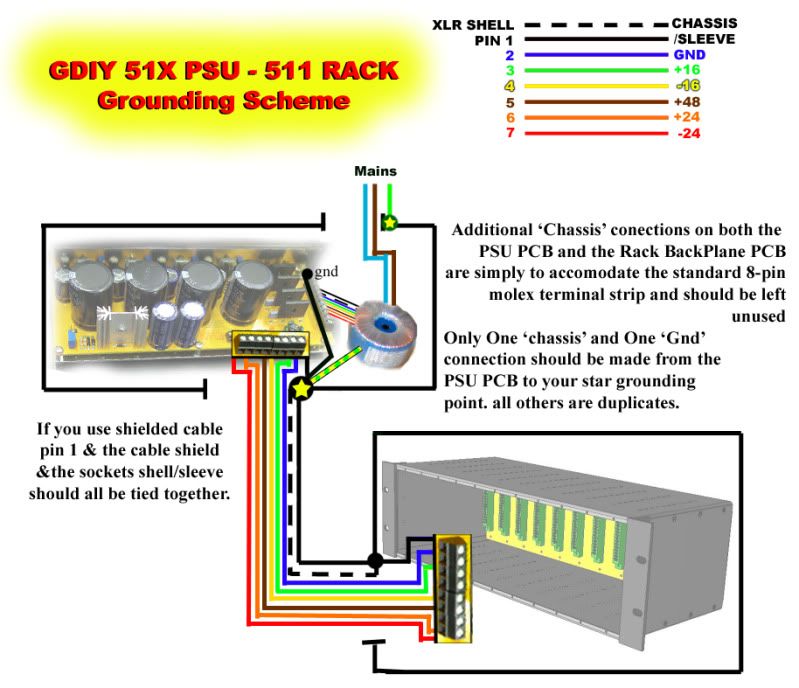
hey, a lot of the information is spread about if its even been discussed.
this is obviously an issue as it keeps coming up, it had me thinking too.
the labelling on the PCBs is very ambiguous and could lead you to make far more connections than are necessary.
I hope you got it sorted but here is what i think for future generations :
hope this is ok with GDIY guys
please tell me if not, or if you have corrections and i will update it/ take it down
this is obviously an issue as it keeps coming up, it had me thinking too.
the labelling on the PCBs is very ambiguous and could lead you to make far more connections than are necessary.
I hope you got it sorted but here is what i think for future generations
:hope this is ok with GDIY guys
please tell me if not, or if you have corrections and i will update it/ take it down
funkymonksf
Well-known member
Very cool Diagram! Can someone from the 51x Crew confirm this..?
kepeb
Well-known member
you'll be lucky ;D
in addition. or before it gets corrected, the rail fuses and LEDs obviously go between the PSU and the 511
the colours i used are just for reference and as a visual guide, as long as the outs from the psu goes to the correct place on the 511 backplane via the fuses, you can use the colours you have, any which way you like.
the two point star grounding in the PSU should give equal or better performance, i was advised this also prevents noise through occurences of stray capacitance in some gear, and hasn't failed me so far.
good luck and enjoy your 511
[silent:arts]
Well-known member
Sir kepeb,
nice work
no fault find at a first glance.
will have a closer look later.
your grounding scheme is to my taste !!!
nice work
no fault find at a first glance.
will have a closer look later.
your grounding scheme is to my taste !!!
shabtek
Well-known member
don't have rack in front of me but a few questions/thoughts arise please allow me to pollute:
I never connect pin 1 on the output/ male xlr on other builds. Always have transformer isolation, never had issue.
Where does the backplane connect to chassis/metal enclosure? through the xlrs?
If so, how can there be a jumper option for chassis ground/ 0volt ground?
I have (untested) built with a wire going from 1 of the 2 'chassis' molex points to a grounding lug lockwasher, and have removed coating from chassis panels at strategic screw holes to assure good continuity.
edit: (here so as minimize thread pollution) the chassis needs a ground for sheilding--it will derive a ground connection through the modules--I'm not there yet.
p.s. I am an ass for not reading the entire thread
[silent:arts]
Well-known member
one of the reasons we have jumpers inside ;Dshabtek said:...
I never connect pin 1 on the output/ male xlr on other builds. Always have transformer isolation, never had issue.
on the PCB the copper plane faced to the back is "Chassis",shabtek said:Where does the backplane connect to chassis/metal enclosure? through the xlrs?
If so, how can there be a jumper option for chassis ground/ 0volt ground?
the other one is "Ground".
the Metalwork of the chassis itself doesn't need any (safety) GND, there is no PSU inside.
gar381
Well-known member
Just finished mine !!
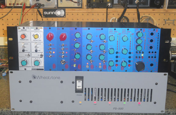
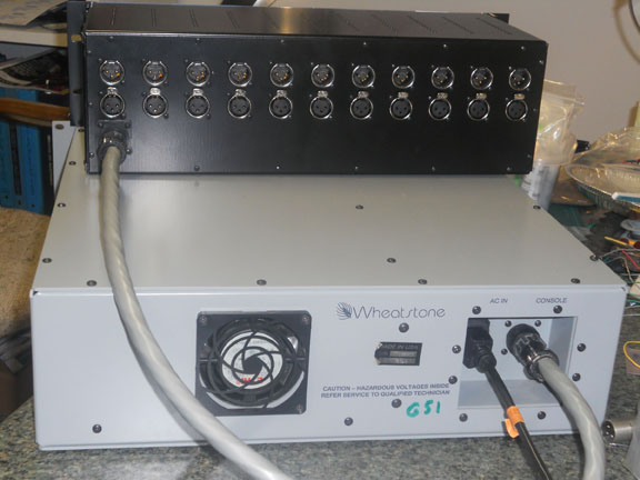
I am using an old Wheatstone desk PSU to power this guy !!
It's a 5 rail PSU with all TO3 case " K" regulators. The 48v rail uses a 317K
regulator and the other 4 rails use 5 amp 338K. All rails are adjustable.
I dropped the +/- 18v rails down to +/-16v. I am only running
the rack at VPR spec at the moment as I nave no 24v modules
or DOAs. I m using a spare Wheatstone PSU connector for the rack
and a Wheatstone PSU cable.
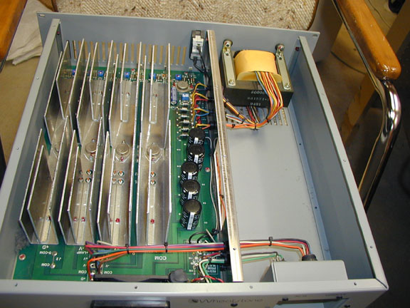
The other 2 rails are 12v and 5v. I will add a 100VA 24-0-24
transformer to the chassis and convert the 12v and 5v rails to +/-24v
for the G51 spec very soon.
This frees up 7 spaces in my DIY 9 space rack so I will be buying
some more Classicapi products from Jeff SOON !!
BTW.. I really need to finish that P.Purpose 525 comp on the far right because
at the moment it has a very airy sound ;D ;D
GARY
I am using an old Wheatstone desk PSU to power this guy !!
It's a 5 rail PSU with all TO3 case " K" regulators. The 48v rail uses a 317K
regulator and the other 4 rails use 5 amp 338K. All rails are adjustable.
I dropped the +/- 18v rails down to +/-16v. I am only running
the rack at VPR spec at the moment as I nave no 24v modules
or DOAs. I m using a spare Wheatstone PSU connector for the rack
and a Wheatstone PSU cable.
The other 2 rails are 12v and 5v. I will add a 100VA 24-0-24
transformer to the chassis and convert the 12v and 5v rails to +/-24v
for the G51 spec very soon.
This frees up 7 spaces in my DIY 9 space rack so I will be buying
some more Classicapi products from Jeff SOON !!
BTW.. I really need to finish that P.Purpose 525 comp on the far right because
at the moment it has a very airy sound ;D ;D
GARY
sahib
Well-known member
Welldone psu Gary. You know your stuff.
Similar threads
- Replies
- 7
- Views
- 1K
- Replies
- 6
- Views
- 2K
- Replies
- 0
- Views
- 766