geoff004
Well-known member
[quote author=[silent:arts]
the only difference between 500 and 51X is the 18pin card edge connector.
which is a problem with some fully enclosure modules.
[/quote]
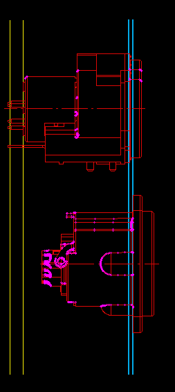
This morning I pulled the side off the rack so I could take a closer look at what was happening with the Chandler.
It appears that the 18 pin connector is keeping the module from seating as far down as it wants to go.
In this instance, pulling the metal chassis off from around the module doesn't help. I'm not sure I want to try to change the 18 pin connector to a 15 pin connector either.
Unless I can find a decent way to grind down the connector I'll probably just live with it.
The unit's been working just fine with the gap.
Thanks for helping me sort this out.
the only difference between 500 and 51X is the 18pin card edge connector.
which is a problem with some fully enclosure modules.
[/quote]
This morning I pulled the side off the rack so I could take a closer look at what was happening with the Chandler.
It appears that the 18 pin connector is keeping the module from seating as far down as it wants to go.
In this instance, pulling the metal chassis off from around the module doesn't help. I'm not sure I want to try to change the 18 pin connector to a 15 pin connector either.
Unless I can find a decent way to grind down the connector I'll probably just live with it.
The unit's been working just fine with the gap.
Thanks for helping me sort this out.

")