Trident a range pre

GroupDIY Audio Forum

Help Support GroupDIY Audio Forum:

This site may earn a commission from merchant affiliate links, including eBay, Amazon, and others.
Hi Tanov, is that waveform simultaneous through the Trident and the Focusright? they look widely different, Ill assume not.

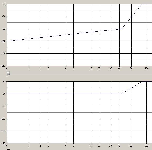
I see the levelling in the Trident waveform you speak of.

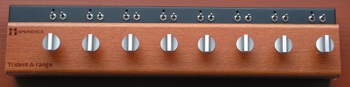
Can you tell us what you have done in respect to gain of the mic amp circuit? I see no gain control in your pictures, does this levelling happen if you reduce the gain of the circuit? what is odd, looking at your waveform, that the levelling happens below the rail voltage...and only in the positive half of the cycle, perhaps it is a bad capacitor...odd indeed.

I have not seen this in our tests.

One area we had problems in was to do with stability at high gain, but who doesn't. The bread board, other early prototypes and the 1st PCB design both exhibited this problem each to a lesser degree, it took much work on the layout, also not using a ground plane was the big one, the mic amp circuit really does not like ground planes.

I have also read reports from Trident users that the consoles did pick up the odd stray RF signal at high gains, could be what we experienced, but this maybe heresy.

So now we have a very stable circuit, that we have tested and tested, and it sounds kick ass!  ;)


My circuit works perfect. This is the original trident module used in 3daudio inc for their shootout CDs. Their samples are distorted - shame!
These are two different sessions. That is way the samples are not identical.
 
ahh well that explains it!

That will be the mastering approach i bet, I see it all the time, it's some dynamics processor, digital i suspect, but could be wrong there..

I've spent many long nights, analysing LOUD cd's, and ive seen that exact thing many times...

Pete


But this is preamp compare CD, so the path must be as clean as possible. Probably that is why they do not use a common microphone to drive all preamps. BTW what do you mean unstable on high gains? HF oscillations?

End regarding mastering - yes, they use hardware limiters to add warmth. To me they add sh*t - high distortion in low frequencies.
The first step of getting loud is to maximize all waves to the top. The next step is to distort it. In this case you receive harmonics, which makes it sound louder. The sonnox limiter has this feature. It is interesting to see how the compression is not applied and the gain is increased dramatically.
 
How interesting - I made an experiment with my previous recordings of a-range and n-12 channels. Because a-range seems to have more accurate frequency range, I subtracted n-12 signal from a-range signal. After that the difference in resulting signal is noticeable - a-range has lots more low frequencies below 70Hz and lots more high frequencies above 4kHz. :) cool.
diff.jpg
 
excellent news all around guys, thanks.

what has been decided for input transformers? I got a peek inside an A Range last week and the sowters are definately the closest but the ratio's don't really seem to line up.

also, I'll be putting mine (hopefully at least 16) into an old Altec 1220 console chassis I have. I'm making the faceplate now, and wondering if I'm going to have to ability with this PCB to select between Mic and line input?
 
Hi Kpearsall,

Ill just chime in about the PCB we are making with respect to MIC/LINE in. It is not built into our PCB per se , but that does not mean you can not do it, If I wanted to have the line input option, you just need to PAD it before the the TX, its quite simple and when release the build instructions we will add some info on how to do it and what to wire to where.

Pete
 
Pad=noise. It is better to use 1:1 line tx with line amp. I am not sure if the circuit is identical to mic.
 
what has been decided for input transformers? I got a peek inside an A Range last week and the sowters are definitely the closest but the ratio's don't really seem to line up.
I think the sowter is close - original says 1.2k:38k which is pretty close to the ratio for Sowter 7456.
The line transformer is 10k:10k, which has a lot of options.

In the original the line input is a completely separate amp - uses 40361/40362 transistors and runs with the 44v supply, while the mic pre is at 24v. 
 
The other option, is that we have the line amp circuit already on the PCB, you can inject straight into that, ive not tried it with a 1:1 tx but i bet that would be fine, ill do a test..

Pete

 
excellent, thank you. I'm going to be adding a summing amp after the channels and obviously noise would be an issue there. Any help is appreciated.
 

Latest posts

Back
Top