Trident a range pre

GroupDIY Audio Forum

Help Support GroupDIY Audio Forum:

This site may earn a commission from merchant affiliate links, including eBay, Amazon, and others.
    The Trident will sound better than any type of built to a budget type consumer/ prosumer gear. Period. Whether or not the difference is night and day or not is  not always as obvious as other times. What could be making the comparison hard is that your running everything through the same board/DA. Looking at the manual for the yamaha n-12 safe to say the inserts are going through some coupling caps and an extra opamp or two before they go to the ADC.  And thats at best. But it could be the boards internal preamp has a more direct path to the ADC's because they are built in and don't require all the protection/conditioning type circuitry found on inputs from the outside world.

    The two do sound more alike the different. Try recording complete songs with these before jumping the gun. There is always a honeymoon period for me before I find what I really find useful about a piece of new equipment ... or don't. And hey if you can't hear a difference worth justifying, then don't build anymore and sell your builds too me for cheep! :D
Good luck!

 
Yes, insert is direct to the ADC, but according to user manual :) probably the service manual will say different things. Maybe I have to build ADC also ;)
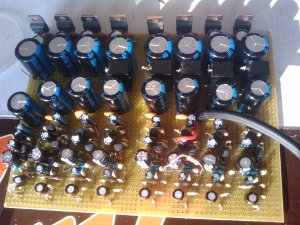
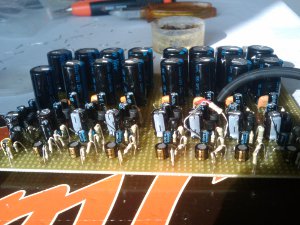
Today I finished the power, phantom power and case. All preamps are ready for final measurements prior to put them in the 2U 19" thing.
 
8ch ready  ;D
trident_top.jpg

trident_front.jpg


The channel with cable and gain resistor is in the recording.

Hey Pete,
What type of switches are you going to use? I saw that you are in UK. I like these:
http://files.rjselectronics.com/pdf/SPC(14-10-2010).pdf
but I cannot order less than 40 of them. It is 5 EUR each :(
 
Thanks Pete.

Can you help with the smudginess? :)

C93=82pF?
R94?
R97?

Is thestuff between R94 and R97 just smudgey crap or should something be connected there?

Thanks!
 
I made up some A range preamps just over a year ago. I compared them against some orignal modules I was repairing and they weren't quite the same. Close though, originals were a little warmer sounding. The lower value caps (2.2uf etc) in the original are tantalums, I'd put in electrolytics. The original modules also had upgraded jensen trafos in, not the oringal zutts, so it wasn't a fair test really. They were from the old lenny kravitz console. I used BC550/560 and BD139/140 transistors, cos that's what I had lying around at the time. Didn't have the original modules for long enough to do some proper investigation.

The one's I made up were cloned from that circuit that was posted, the 2038 module. I also encountered a bit of an RF problem, the only solution I found was to add a common mode choke and a couple of caps (same circuit as on the mic pre i/p on ssl E/G mic pres) Our studio has always had a bit of a ground problem anyway, so you might not come across this. But the A-range had a reputation for picking up RF anyway from what I've heard.

They do sounds great though, we did a mic pre shoot out with the tridents, neve 1095s, GML, hardys etc. The a-range's were right up there, like the neve's but a bit faster, more transients. Noise level was better than the neves, overall they were closest to the GML pre's, funny cos they're a very different beast....

I put some extra positions the mic pre switch, original circuit goes in steps of 10dB. I added some values to get 5dB steps

20db 13k
25dB 5k6
30db 3k
35dB 1k5
40dB 820r
45dB 470r
50dB 270r
55db 150r
60dB 82r

If you put the output line driver stage in, you can reduce the negative feedback on it with a dropping resistor to boost the gain further. This could be done on the gain switch to get a 65dB and 70dB setting if you're feeling clever!?

I also added an output trafo, sowter 8403x 1:1. Just for sh*ts n giggles. I ran the whole thing off 30V, draws something daft like 2mA per circuit. You don't even need a regulator, just run it off a zener diode. Quite a cheap build, until you buy the transformers
 
njm said:
If you put the output line driver stage in, you can reduce the negative feedback on it with a dropping resistor to boost the gain further. This could be done on the gain switch to get a 65dB and 70dB setting if you're feeling clever!?

Hi Njm,

I have done exactly that, its a dual gang switched pot, that controls the negitvie feedback of both amps.

cool, well it sounds like we have almost built it in the same way, but it is interesting that you say the eltrolytics were better. infact i have foot prints for either on our PCB, so far only used Tantalums in our testing and ive found no issue with them so far.

best
Pete
 
haha no i used a single gang lorlin for the gain switch and set the ouput amp for 10dB gain, with a 100k pot (with a res to ground) inbetween for a +-10dB trim. Not sure about the difference in sound, hopefully I'll get some more original modules in to repair and do a bit of A/B testing. Maybe it's the transistors I used, I just plucked out some ones with similar hfe and suitable voltage ratings. I never tried testing them without the output trafo either. As it is, they sound great. Why change it!?
 
Hi Njm,

Regarding lorlin, are you using shorting or not shorting one?

Regards,
Vladimir
 
mitsos-

wild uneducated guesses these are

C-93 is probably 22pf (most fb caps in the 2038 are 22)
R-94 might be 8.2k
R-97 could be 68R  

1038 is different than the 2038s here

the differences are posted a few pages back.
still haven't done a schemo of the input yet


I use the same values. I saw them from the hard to read 3-4-79 schematic.

BTW any thoughts regarding 2 identical 1 MOhm resistors in the gain switch?
In the 03-04-79 schematic there is a constant resistor to ground and it is smaller.
 
The two 1M resistors on the gain switch are only in circuit when the module is in line input, you don't need to worry about them. I used a non shorting switch with the values I posted earlier in series with the 220u cap, no extra 1M stuff. Come to think of it, it would make sense to put a 1M in there constantly to keep the negative side of the 220u cap at ground to prevent clicks, but I didn't. Ooops. Use a non shorting switch, when switching between gain settings the circuit will go low gain on you won't get any funny noises. :D

cheers
Nick
 
I thought the same, but there is separate line amp, so do you need to power the mic premp? Also the mechanic relation between the line and mic gain is not shown.
 
QUEEF BAG said:
mitsos-

wild uneducated guesses these are

C-93 is probably 22pf (most fb caps in the 2038 are 22)
R-94 might be 8.2k
R-97 could be 68R  

1038 is different than the 2038s here

the differences are posted a few pages back.
still haven't done a schemo of the input yet
cool thanks. Will see if I can't breadboard one of these...

Anyone know if Daking use the sowter in theirs?
 
Back
Top