scott_humphrey
Well-known member
chunger said:UPDATE:
We are now on revision 1.2 of the C12 pcb set. Only the slightest of changes was implemented on the revision. The board was lengthened by .060" to give slightly more length to the output capacitor slot. The V-cap 250V 1uF OIMP type capacitor now fits without mods. Since the kit-supplied Erse units have been working superbly in stock .56uF and 1uF options, I have not had a chance to test these super-expensive caps that are likely more snake-oil than actual "sonic gold" in our application. There was discussion about extending the PCB length all the way down to the base of the mic to facilitate easier mounting of the AMI or Cinemag transformer, but recent tests of the clone against vintage original early type C12 leave the question open about whether the larger core early-style transformer may be a better performing setup overall. Inquiries to Oliver at AMI about possible development of such a reproduction transformer have gone unanswered so far, but I can try Cinemag and other capable transformer specialists to see. Anyways, the short story is I would like to leave enough space at the bottom of the mic for the larger core transformer should that ...
New products are in the pipeline:
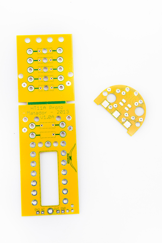
1. "prototyping" pcb set for the HT-11A microphone. This board is similar to the C12 PCB set but has no traces except for the tube heater supply voltage. Teflon standoffs in press-fit configuration at the top of the mic will allow for traditional turret-board style wiring of C12, ELA M251, or any number of other mic configurations desired. For those who would like to experiment with a point-to-point type tube mic build, this is a clean platform to do so in the HT-11A body with minimal fabrication and fitting of parts.
I put Cinemag transformer inside of the transformer case that came with the microphone, and I feel that this option should be preserved for future iterations. Seems more eloquent than using ties, IMHO....
Also, regarding the new board, there is probably no reason to have traces for the heaters on the boards. Simply run twisted cables right up to the tube. Keeping the high current heater leads off the board makes sense, at least theoretically.
Finally, I'm glad to see that the teflon standoffs will be press fit. I modified the current boards to isolate the high impedence part of the circuit from the board, and the difference in sound is subtle, but real. The modifed mic seems to have slightly more body/bass. The mic now sounds more [insert your favorite audiophool superlative here].
Thanks again for your great work!


