Mini SSL 5000 Mixer build thread (Revisited 2015)

GroupDIY Audio Forum

Help Support GroupDIY Audio Forum:

This site may earn a commission from merchant affiliate links, including eBay, Amazon, and others.
Ok guys after powering up my EQ modules, i decided to test the audio on them, and hooked up some temporary XLR's to the input and output moles headers on the EQ bus card.
I plugged up a tone generator to the input and an analyser on the output, set the generator to send 0db of 1khz tone.
The audio is not passing though the EQ whether i switch the EQ in or out,
with the tone switched off im getting -80db with it on im getting -60db so a tiny bit is bleeding through.

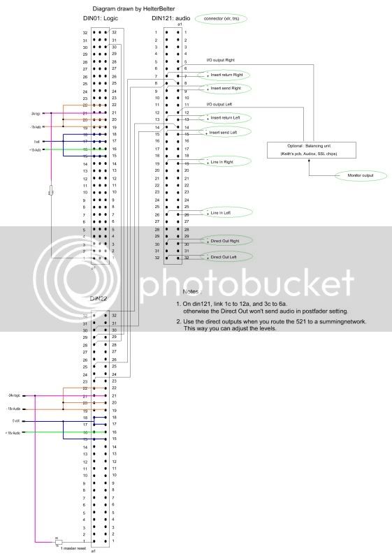
FYI i have pinned up as follows:

0V Pin 12c,14c,17c,18c
+18V Pin 16c
-18V Pin 19c,20c,22c
-25V Pin 21c
Master reset pint 1a tied to -24V through a 22KOhm resistor.

Out - Pin 29c
Out + Pin 30c
In - Pin 31c
In + Pin 32c


I didnt pin up the 6v i suspected i needed as it just says its for lamps on the pinout diagram.

Is there something obvious anywhere that ive missed out than somebody can see?

ive tried several of my 13 stereo and 4 mono EQ's and none of them are working so dont think they are all faulty.

Hopefully ive missed something really simple  :'(
 
You certainly missed something vital, and posted here so many times..... Without the balancing hybrids, the balancing lines don't work.

Use the unbalanced lines :
30 A in
32 A out.

Also tie 28A via a resistor to the -25 volt line.
Strap the +VE Lamps to 0v.

;D
 
ah ha  !
Perfect  thank you ive tried it with a mono compressor (without balancing hybrids) and its now working :)
I do have some balanced mono EQ's i tried and it still wasnt working before these bits you have mentioned but il try them with the unbalanced connections on them tomorrow,
Also my stereo EQ's are all balanced so in theory shoulda worked?
Although i hadnt strapped 28A to -25v or +V Lamps to 0v so maybe thats why it wasnt working.

I did build a dual mono racked unit a year or so ago and thought i had all the documentation sorted but obviously missed those parts,

Thanks very much for the help, i was feeling a little deflated after none of them working at all  :D
 
helterbelter do you have the pinouts for unbalanced line on the Stereo EQ's?
i dont seem to have them,
I know the left channel is the same as the mono but i dont know what the right channel pinouts are,
I seem to be missing the EQ card backplane sheet from my documentation.
Thanks
Neil
 
Hey Neil,

I haven't got the docs here at work.  But if you check the Connector cross reference of the 521 module, you'll see which wires of the S502 cable connects to the 520/522, and also which pins will be the in and output of the audio.
 
I made this diagram a few months ago, I forgot I had it in my photobucket.... :

JUST TO BE CLEAR :
This is only for standalone racking.

SSL522wiringdiagram.jpg
 
You're welcome  :D


I still have to dig up the 524 papers...

speaking of 524's, you said they're NOS, right ? Maybe I'm interested. I have a few 524's, but IIRC they're not that fresh anymore. A recap will probably do the trick, but I've got lots of other things to do in the console project that have more priority. Besides, nonpolar 220uF's aren't very common....
 
Ah cool thanks, I couldn't get on here yesteday because the forum was down for maintenance , I will email you about the 524's
 
Ive finally managed to get a bit of time and completed my IMO Summing rack for my 5K mixer build and it actually works ;)
http://www.groupdiy.com/index.php?topic=43999.0

Im also in the process at the moment of hooking up my 521 input modules to my 522 EQ's via some SL502 Bus cards and ive struck a problem that perhaps you may be able to help with?

Is the only connection that is needed between the SL502 and the SL521 the 10way IDC (S502) ?
ive followed page 28 of the SL520 documentation and connected:
Pin 2 of the IDC to 14c of the DIN121
Pin 4 of the IDC to 14a of the DIN121
Pin 5 of the IDC to 32c of the DIN1
Pin 7 of the IDC to 30c of the DIN1
Pin 8 of the IDC to 8c of the DIN121
Pin 10 of the IDC to 8a of the DIN121

i have also connected pin 1a of the SL522's to -24v via a 22K Resistor.

The 521 is working fine and passing audio, the 522 is powered up fine too but if i press the IN button on the 522 to engage the EQ the sound cuts/mutes  ???.

Can anyone see something ive obviously missed out? or done wrong at all, im somewhat confused :(
 
Thanks Paul, I totally missed out the connections between the Din 121 ans Din 22 the only connections i had made were the SL502, cant wait to get back to work to give it a try!
 
It works !!!

OK i didnt realise that what you show in your diagram, is what i did already have connected, except it was all done via the S502 IDC link,

Ive added this to your drawing here:


Uploaded with ImageShack.us

The reason it wasnt working was that i had linked a wrong pin to -24V via a resistor, as soon as i removed that it all worked  ;D

Now ive just got to copy it 15 more times and get it all in the rack, but the difficult bit is now done!

Thank you so much for your help Paul!
 
DigitalMetal said:
It works !!!

OK i didnt realise that what you show in your diagram, is what i did already have connected, except it was all done via the S502 IDC link,

Ive added this to your drawing here:


Uploaded with ImageShack.us

The reason it wasnt working was that i had linked a wrong pin to -24V via a resistor, as soon as i removed that it all worked  ;D

Now ive just got to copy it 15 more times and get it all in the rack, but the difficult bit is now done!

Thank you so much for your help Paul!
GREAT Neil!!!

Glad you got it sorted-and thx a lot for the additions in Paul´s diagram!

Rock on,

Udo. :D
 
Hi Neil,

glad to hear it works now !
I guess it's the pin 28a that's needed for standalone racking of the eq/dynamics that you've connected. Am I right ?

Then I owe you an apology.
I haven't said with the posting the 522 standalone wiring, that it's solely for standalone racking...... so I have added it.


DigitalMetal said:
Ive added this to your drawing here:
.............................................................

It's great that you've added more info in this diagram. That's what this great forum is about !

Unfortunately, the diagram that you used here, is not something I have shared in public.  It's made to show the wiringconnections between the 521, 522, and 520, but it's not correct, as the 520 doesn't work this way. I believe I have noted in the email when I sent it to you, that it's not tested yet. If I haven't, then I apologise.
So, the 2nd Din22 should be removed. At first I expected the 520 would work here (like the 510 works with the mono input and eq combo), but it doesn't. So...... could you remove the 2nd Din 22 from this diagram ? Then we don't share faulty info.

In case it's difficult to remove it , I can alter the original file and post it here. Let me know what you prefer.
 
No the wrong pin was a different one, it was about 4am whan i was wiring it up so i should have expected to make a mistake ha ha.

Sorry about uploading the diagram, you probably did tell me but you must know me by know i need to be told everything twice ha ha!

Ive fixed it and modified my post of the diagram.

 
Getting there slowly, please escuse the dodgy wood work its going to be sanded and covered in something when its finished,

Merry Christmas Everyone!

383085_10150512438436201_711511200_10997252_514676207_n.jpg
 

Latest posts

Back
Top