All things G1176 - the new "repost" thread.

GroupDIY Audio Forum

Help Support GroupDIY Audio Forum:

This site may earn a commission from merchant affiliate links, including eBay, Amazon, and others.
Thanks Geoff, I found this quote from Mnats which also helped clarify...

[1, 2, B, C are correct.

3 on the pushbutton should go to 6 on the rotary board - R51 to pad Y.

12 on the pushbutton should go to 9 which is connected to pad X. These latter two are for the +4 setting so they need to connect to the output on the line amp.

4 goes to 4 = ground. Correct, but the designations are confusing since there is also a pad 4 on Jakob's layout.

A goes to A = pad 22 which is also point 22 on the schematic. So that is also correct.
/quote]

Now I understand 4 is ground.
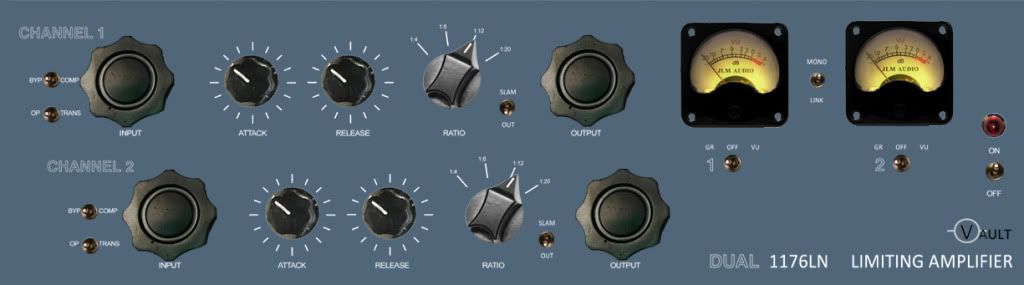
I think my build is going to have three toggle switches per channel now, plus the "stereo=Mono" link toggle. A separate switch for GR Disable / Enable.

I do like to complicate things!

;) Mac.
 
Now that I have figured this all out, I thought I would post it here in case others are doing a build that is intentionally try not to look like the original - and is using as many easy to find cheap switches as possible (like me)  ;D

Here is the concept for the front panel.

frontpaneldesign4copy.jpg


So the switching is as follows;

Byp / Comp = 2 position SPDT connects pad 4 and pad 22 for Byp - Open for Comp
Op / Trans =  2 position DPDT connects + and - pads for transformer in or switches to Op Amp input (both grounded to shield of input- not switched).
Ratio = simple four position alpha taking care of ratio duties
Slam / Out = 2 position DPDT switch shorts ratios 20 and 4 as per Gyraf's drawing (SWa SwB)
nuke_sw.gif

GR / OFF / VU = meter switching 3 position DPDT (on off on) simple x and y on one side, pads 28 and 29 on the other, meter + and - on the centre.
Mono / Link = SPDT to link stereo inteconnects or unlink (mono)


I think after two years of thinking this through it might actually becoming a reality!!

cool,
Mac  :)

 
Does anyone see any errors with my toggle switching arrangements?

Byp / Comp = 2 position SPDT connects pad 4 and pad 22 for Byp - Open for Comp
Op / Trans =  2 position DPDT connects + and - pads for transformer in or switches to Op Amp input (both grounded to shield of input- not switched).
Ratio = simple four position alpha taking care of ratio duties
Slam / Out = 2 position DPDT switch shorts ratios 20 and 4 as per Gyraf's drawing (SWa SwB)
GR / OFF / VU = meter switching 3 position DPDT (on off on) simple x and y on one side, pads 28 and 29 on the other, meter + and - on the centre.
Mono / Link = SPDT to link stereo inteconnects or unlink (mono)

cheers,
Mac.
 
mac said:
Does anyone see any errors with my toggle switching arrangements?

Byp / Comp = 2 position SPDT connects pad 4 and pad 22 for Byp - Open for Comp
Op / Trans =  2 position DPDT connects + and - pads for transformer in or switches to Op Amp input (both grounded to shield of input- not switched).
Ratio = simple four position alpha taking care of ratio duties
Slam / Out = 2 position DPDT switch shorts ratios 20 and 4 as per Gyraf's drawing (SWa SwB)
GR / OFF / VU = meter switching 3 position DPDT (on off on) simple x and y on one side, pads 28 and 29 on the other, meter + and - on the centre.
Mono / Link = SPDT to link stereo inteconnects or unlink (mono)

Just my opinion but i would short ratio's 20 and 12 for an even higher ratio. For that matter, why don't you use a 4PDT do make it all buttons in. Also, I don't really understand the off for the meter. A two position on-on switch will be cheaper. Plugins have off positions for meters to save DSP and cpu power. Everything else looks great and your faceplate looks great. Put up some pics when you get it all dialed in.

Brandon


cheers,
Mac.
 
Cheers Brandon,
I was of the understanding that "all in" was really just the 20 and 4 ratios together anyway (I am sure Geoff mentions this on his site?? - but perhaps I have oversimplified and missunderstood).

I just powered up my first board to undertake Q measurements and R41 started burning :(

I of course ensured PS was -10 and +30 spot on prior to connecting power to the main boards and double checked the datasheets for - Q6, Q7, Q8 and Q9 are all connected the right way prior to switching on.

For this test I left off the Q1 and Q10 Fets and the two IC's off the board also (incase of first power up burning). I also didnt have my output trannie or input pot wired up for this test but this shouldn't matter, should it?

I have double checked polarity of c15 c* and c14 - all good. Removed R41 (which in my case is 3R3 and 1R0 carbon resistor in series), and checked with my multimeter but still measures 4.3 ohms.

mmmmmmm...head scratch....??
Mac.

 
All buttons in, is in fact what that says. All buttons in. 4,8,12,and 20 all pushed in together.which makes it to my understanding and anyone correct me if I am wrong about 7680:1 ratio. Sorry to hear about R41. I am sure in your case as in most it is something minor. Did you use two resistors in series on R40 as well. I assume they didn't burn up. All resistors should be 1/4 watt. make sure they are not 1/8 watt. What is the voltage where R40, R41 C14 and C15 come together. Resistors burning is usually the cause of too much resistance for the power rating. sounds like you have too much voltage at this spot or the wattage for this is to low. If you can and for trouble shooting later try not to deviate from the original schematic and use a 4r3 resistor here. Hope you figure it out. I sold my last 1176 and in the process of building more so unfortunately I can't give you what voltages you need for this spot. Hope you figure it out!

Brandon 
 
casrec said:
All buttons in, is in fact what that says. All buttons in. 4,8,12,and 20 all pushed in together.which makes it to my understanding and anyone correct me if I am wrong about 7680:1 ratio.

Not sure what the ratio is, but looking at the circuit the middle two buttons are superfluous when pushing them all in. Just the end two have an effect. This would make the ratio more like 80:1, but I doubt it would be this high. I must take a measurement of the transfer curve when this mode is activated next time I have one on the bench...
 
Interesting. I will have to get a meter out when I am done with my next ones. I do know and this might not have any relevance, but with just 20 and 4 pushed in the meter does not peg all the way. about +3 on the meter. remove 4 and push in 8 it almost pegs. Remove 8 and push in 12 and it pegs. Push all of them in and it pegs. So with this theory wouldn't all buttons in only using 20 and 4 make the meter not peg. Are we talking about gryaf's rotary version slam or just all buttons in mode period. is it the same no matter what. I here a difference with 20 and 4, 20 and 8, 20 and 12 and all buttons in. all buttons in sounds different then just 20 and 4.

Brandon 
 
Thanks Brandon,
Yes both resistors are 1/4 watt.

For taking the Q measurements is it OK to leave the Q1 and Q10 Fets and the two IC's off the board also. I see from previous pages in this thread that leaving the Fet's off is good insurance til you iron out other bugs, but what about the IC's.

Mac.
 
Just a quick look at the circuits, here's an examination of the electrical effect of pressing all the buttons:

http://www.axtsystems.com/index.php?option=com_content&view=article&id=85:1176slammode&catid=34:1176ln&Itemid=62

Hopefully I'll get around to performing some measurements from a unit to see what happens to the compression curve.
 
casrec said:
I do know and this might not have any relevance, but with just 20 and 4 pushed in the meter does not peg all the way. about +3 on the meter. remove 4 and push in 8 it almost pegs. Remove 8 and push in 12 and it pegs. Push all of them in and it pegs. So with this theory wouldn't all buttons in only using 20 and 4 make the meter not peg.
Brandon   

I've done the slam mod with a DTDP toggle which connects the 20:1 and 4:1 ratios together, my meter definitely pegs to the right and it sounds as it should, absolutely crazy!  8)

Mark
 
I am not disputing that gryafs slam mode with a toggle is not the same as all buttons in. I am sure it is doing the same as UA's 2-1176 rotary. What I am saying, with push buttons, pushing in all the buttons sounds and reacts differently then just pushing in 4 and 20. Or 4 and 8, or 8 and 20 and so on and so on.

brandon 
 
If you can and for trouble shooting later try not to deviate from the original schematic and use a 4r3 resistor here.

Is 3R3 and 1R0 carbon resistor in series, deviating from the schematic? I could not get 4r3's. (it does appear as though it is just the 1R0 that is burning).

Also, for taking the Q measurements is it OK to leave the Q1 and Q10 Fets and the two IC's off the board ??

thanks for the help guys.

Mac
 
mac said:
If you can and for trouble shooting later try not to deviate from the original schematic and use a 4r3 resistor here.

Is 3R3 and 1R0 carbon resistor in series, deviating from the schematic? I could not get 4r3's. (it does appear as though it is just the 1R0 that is burning).

Also, for taking the Q measurements is it OK to leave the Q1 and Q10 Fets and the two IC's off the board ??

thanks for the help guys.

Mac

3R3 in series with 1R0 will give you 4R3. These resistors should not be getting hot. If they are then you need to examine the bias conditions of these transistors and also Q6, A7.

If you are performing Qbias calibration then you need to have all the components in place.

Did you perform a check of all the DC bias conditions for the transistors? This should be one of the first steps.
 
Thanks Geoff, just to clarify I understand that all components would need to be in place for calibration of the unit. By "Q measurements" I just meant taking voltage measurements of all the transistors (as per first page of this thread) to check operation of the board, which I havent done because as soon as I saw smoke I powered off the board.

Is this what you mean by dc bias conditions check?

Mac
 
Yes. That's correct.
Since you have verified that your supply rails are correct (+30/-10V), then you should be OK with the FETs and opamps in circuit (provided you put them in the correct way).

If you are smoking the emitter resistors fro Q8 and Q9 then you need to check very carefully around this area of the circuit for wrongly inserted components and wrong values. Make sure you have the correct transistors mounted in the correct holes fro Q8 and Q9.
 
mac said:
If you can and for trouble shooting later try not to deviate from the original schematic and use a 4r3 resistor here.

Is 3R3 and 1R0 carbon resistor in series, deviating from the schematic? I could not get 4r3's. (it does appear as though it is just the 1R0 that is burning).

Also, for taking the Q measurements is it OK to leave the Q1 and Q10 Fets and the two IC's off the board ??

thanks for the help guys.

Mac

I was just saying this because you now have two components to worry about instead of one. Also i would double check the wattage of these resistors. Don't really understand why one would burn up and the other wouldn't.
 
Yes thanks again Brandon. I agree with your advice. I am rapidly learning that success in DIY is about checking, rechecking and eliminating assumptions I may be making along the way.
As you say, the more potential for mistakes one can eliminate - more likelihood of success.

cheers,
Mac
 
and I am sure you will have success. Again, great design and faceplate and make sure you share some pics when you get it all done.

Brandon
 
Cheers, Brandon.

Both resistors are getting very hot as are Q8 and Q9 - within seconds of powerup.
I think I am just noticing the smoke off the 1R0 first but its all getting hot.

I am not sure what else to check - rechecked the datasheets for my Q8 BD135G, Q9 BD136G, Q6 and Q7 BC560. I also rechecked CR1 and 2 because the ones I got dont have a marker band to indicate cathode.

Wierd but resistance check with a DMM shows no clear forward bias - gives me the same reading in both directions?? i am going to investigate these diodes further....
 

Latest posts

Back
Top