All things G1176 - the new "repost" thread.

GroupDIY Audio Forum

Help Support GroupDIY Audio Forum:

This site may earn a commission from merchant affiliate links, including eBay, Amazon, and others.
Hi Mac,
if you want to have an idea of all the ALL function works, you can use the Bomb Factory BF76 plugin.
although the sound of the plugin is different than hardware units , bomb factory did a great work in capturing the compression characteristics of the 1176.

So try to use the ALL function in the plugin applied to some drums, and then you can make up your mind if you want it. I'm  sure if you don't like it in the plugin you will not enjoy also the real one.

regards
 
Thanks for everyones input - I think i shall invest in two double decka alpha 5 pos switches and wire my ratio's as per mnats guide - dont want to miss out on any of the potential of this unit (and more likely for me not to stuff it up if I stay as per Mako's guide).

One more question in relation to meter switching. I am planning to use a three pole three position toggle to switch my meters, and from this thread and other searching am trying to confirm how to wire mnats meter boards (or if i even need to use them in the case of using a toggle switch).

From the schematic and mnats wiring guides, I understand that for GR Off this is pad 4 and 22 shorted, GR = pads 28 and 29 connected to - and + of the meter and Output VU is just x and y (including R51) switched to - and + of my meter.

Is this correct? If it is, then i dont really need the meter board (do I?) and can just wire straight to the back of my toggle switch I presume.

Mac.
 
gswan said:
goldenGeek said:
Sorry about that one, I`m a bit rusty at english so I guess I was quite sloppy there. I KNOW that it`s the right way :) My meter shows the output level, but from time to time it seems like the levels get stronger or weaker without turning any knobs, and sometimes the sine wave gets distorted (the tops and bottoms gets flat, I guess this is distortion..?).

Sounds more like a bad solder joint in the first gain stage causing it to lose the feedback and clip.

I have now replaced all the transistors just to be sure I didn`t screw up something like I did on my first unit (bending the legs too hard). And I`ve looked over (and re-soldered some just in case) the solder joints, they seem fine to me. It seems like there`s no change, but I`ve investigated a bit further. When the unit is powered up (in VU mode) it gets tons of gain making my signal generator distort at 9 o`clock and the output meter is dead still on full peak. Then I turn down the input volume and output volume and output on the generator to get a steady 0 db output. Then I wait about 30 seconds and then the signal start to drop slowly down to extremely low (the VU shows nothing and the controls needs to be turned really loud, full input and output reads about -8 db on my VU). If I switch to GR mode and power off and on again (and adjust so that the GR shows 0db), the needle drops to about -15db after the normal loud period. Turning up/down the input doesn`t seem to start compression - this goes for both the first loud period and for the later silent period. Could this be an indicator of some messed up condensers and/or diodes? Or is there something else that I`m missing? I`ll start measuring values now, hopefully that will generate some useful info :)
 
goldenGeek said:
gswan said:
goldenGeek said:
Sorry about that one, I`m a bit rusty at english so I guess I was quite sloppy there. I KNOW that it`s the right way :) My meter shows the output level, but from time to time it seems like the levels get stronger or weaker without turning any knobs, and sometimes the sine wave gets distorted (the tops and bottoms gets flat, I guess this is distortion..?).

Sounds more like a bad solder joint in the first gain stage causing it to lose the feedback and clip.

I have now replaced all the transistors just to be sure I didn`t screw up something like I did on my first unit (bending the legs too hard). And I`ve looked over (and re-soldered some just in case) the solder joints, they seem fine to me. It seems like there`s no change, but I`ve investigated a bit further. When the unit is powered up (in VU mode) it gets tons of gain making my signal generator distort at 9 o`clock and the output meter is dead still on full peak. Then I turn down the input volume and output volume and output on the generator to get a steady 0 db output. Then I wait about 30 seconds and then the signal start to drop slowly down to extremely low (the VU shows nothing and the controls needs to be turned really loud, full input and output reads about -8 db on my VU). If I switch to GR mode and power off and on again (and adjust so that the GR shows 0db), the needle drops to about -15db after the normal loud period. Turning up/down the input doesn`t seem to start compression - this goes for both the first loud period and for the later silent period. Could this be an indicator of some messed up condensers and/or diodes? Or is there something else that I`m missing? I`ll start measuring values now, hopefully that will generate some useful info :)

Could by a number of things. Check for electro's reversed in signal amplifiers.

Forget the meter on the unit itself, it could be messed up. Use an external, calibrated audio millivoltmeter or equivalent to be sure of what you are reading. Then start probing to see where the signal starts to disappear.
 
gswan said:
Could by a number of things. Check for electro's reversed in signal amplifiers.

Forget the meter on the unit itself, it could be messed up. Use an external, calibrated audio millivoltmeter or equivalent to be sure of what you are reading. Then start probing to see where the signal starts to disappear.

that`s a pretty quick reply :) Thanks :)
I`ve checked the electros and they are all the right way. I`ve also had my scope hooked up to the output and it acts just the same way as the VU, so I guess there`s time to start probing for the evil component ;)
 
goldenGeek said:
gswan said:
Could by a number of things. Check for electro's reversed in signal amplifiers.

Forget the meter on the unit itself, it could be messed up. Use an external, calibrated audio millivoltmeter or equivalent to be sure of what you are reading. Then start probing to see where the signal starts to disappear.

that`s a pretty quick reply :) Thanks :)
I`ve checked the electros and they are all the right way. I`ve also had my scope hooked up to the output and it acts just the same way as the VU, so I guess there`s time to start probing for the evil component ;)

Yes, better even with a scope. Disable the GR, run a 1kHz signal through it and start probing.
 
I want to use both rotary switch PCBs, but a separate toggle switch for the "GR OFF". I can't get it together. How should I hook up the switch?
 
ChrioN said:
I want to use both rotary switch PCBs, but a separate toggle switch for the "GR OFF". I can't get it together. How should I hook up the switch?

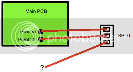
The GR disable switch is a SPDT switch that connects the GR amp input to GNS for disable, and to the output of the ratio switch divider when enabled.
 
Thanks alot! I'll have to do some thinking here. Whats the easiest way of doing this?

gswan said:
ChrioN said:
I want to use both rotary switch PCBs, but a separate toggle switch for the "GR OFF". I can't get it together. How should I hook up the switch?

The GR disable switch is a SPDT switch that connects the GR amp input to GNS for disable, and to the output of the ratio switch divider when enabled.
 
Point (22) on the circuit.
Connect the common terminal of the switch to the mail PCB point (22).
Connect one end of the switch to GND and the other end to the wire that would normally go to point (22) on the main PCB.
 
Excuse me for being thick, I don't quite get where the "last" wire should go:

Bild4.png


gswan said:
Point (22) on the circuit.
Connect the common terminal of the switch to the mail PCB point (22).
Connect one end of the switch to GND and the other end to the wire that would normally go to point (22) on the main PCB.
 
ChrioN said:
Excuse me for being thick, I don't quite get where the "last" wire should go:

Bild4.png


gswan said:
Point (22) on the circuit.
Connect the common terminal of the switch to the mail PCB point (22).
Connect one end of the switch to GND and the other end to the wire that would normally go to point (22) on the main PCB.

The wire that would normally go to pin 22 of the main board would go to the ? pin of the switch. This comes from the ratio switch divider.
 
gswan said:
The wire that would normally go to pin 22 of the main board would go to the ? pin of the switch. This comes from the ratio switch divider.

Hmmmmm, that makes total sense.

IIRC I ran a wire from the already connected point (22) to ground through a switch in my build and it works as expected.
 
Your question was good timing ChrioN, as it deals with my question too..I am trying to wire up using a three position three pole toggle for GR Off, GR, Output.

From the schematic and mnats wiring guides, I understand that for GR Off this is pad 4 and 22 shorted, GR = pads 28 and 29 connected to - and + of the meter and Output VU is just x and y (including R51) switched to - and + of my meter.

Is this correct? If it is, then i dont really need the meter board (do I?) and can just wire straight to the back of my toggle switch I presume.

So from what you are saying GR off is just pad 22 to ground, not to pad 4 ....pad 4 just goes to the ratio board and doesnt appear to ground....now I am confused...

Mac.
 
When in 'disable' mode, the input to the GR amp (22) must be connected to GND.
When not in 'disable' mode, the input to the GR amp (22) must be connected to the output from the ratio switch.
 
Back
Top