You are using an out of date browser. It may not display this or other websites correctly.
You should upgrade or use an alternative browser.
You should upgrade or use an alternative browser.
All things G1176 - the new "repost" thread.
- Thread starter orson whitfield
- Start date
Help Support GroupDIY Audio Forum:
This site may earn a commission from merchant affiliate
links, including eBay, Amazon, and others.
audiophreak
Well-known member
Hi All ,
O.K. .... I built thr PRR test circuit and performed the test as described on the 5 FETs I gleaned from the NRG test procedure, then put the same 5 through the gwan procedure, then the same 5 through the PRR procedure.
I realize ( sometimes on a daily basis ) how my Newbness shines through ... but at least in this experience, it seams that the NRG procedure is kind of a quick way the group FETS that have a single similar test point , then gwan's and PRR's procedures get more detailed as to cuve/slope - actual operating point readings.
The 5 FETs tested very well I think in the more detailed tests - in the attached gwan Spreadsheet, in the Id(mA) side of the graph I put the " V " readings from the PRR proceadure , ( they were all( -1.xxx vdc ) so I just left off the( -1 ) to work in the graph, and just repeated the last reading so the graph flatlined - all 5 are very close and feel confident that I have very closely matched FETS
Thank you gswan, Echo North, gemini86, PRR, .. cool stuff ;D
Attachments
audiophreak
Well-known member
Heloooo ,
I'm sorry ... a little confused ... for the Lundahl input orientation for 2:1 step down ... is the ground pin closer to / or further away from the XLR input pads on the PCB ?
I'm sorry ... a little confused ... for the Lundahl input orientation for 2:1 step down ... is the ground pin closer to / or further away from the XLR input pads on the PCB ?
audiophreak
Well-known member
OK .... maybe a little more information - I was working off of this information from mnats page - Lundahl Input Options
... the LL1540 fits the PCB in both orientations ... so what way is " as usual " ? using the direction found on mnats page for the output transformer using the ground pin
-- is the ground pin on the LL1540 closer to , or further away from the input pads for the 2:1 configuration ?
Many Thanks !
As originally conceived by Jakob, the Lundahl input transformer option is configured as a 1:1 ratio circuit. PRR pointed out in his post that a step-down configuration is preferable in this circuit. This is easy to accomplish with my latest revision boards.
Lundahl Input Options
Find the area just to the right of the transformer like the above image. Cut the trace marked in red on the reverse side of the PCB. It is easy to find as it runs diagonally and is thinner than the other tracks. Now run wire links between the pads as marked in blue. The two resistors marked R*1 and R*2 are not installed in the 2:1 configuration.
Next, install the Lundahl LL1540 input transformer as usual. It will now operate as a 2:1 stepdown transformer.
... the LL1540 fits the PCB in both orientations ... so what way is " as usual " ? using the direction found on mnats page for the output transformer using the ground pin
-- is the ground pin on the LL1540 closer to , or further away from the input pads for the 2:1 configuration ?
Many Thanks !
audiophreak
Well-known member
ok ... I down loaded the LL1540 Data sheet , compared it to the PCB, and figured it out ;D so for future reference : the " usual " orientation of the LL1540 is with the ground pin further away from the optional input pads.
s2udio
Well-known member
If you search you will find........all the info to get you up and running!
You will need more than just the schematic................READ.
http://www.axtsystems.com/index.php?option=com_content&view=article&id=76:1176project&catid=45 rojdownloads&Itemid=78
You will need more than just the schematic................READ.
http://www.axtsystems.com/index.php?option=com_content&view=article&id=76:1176project&catid=45
Kingston
Well-known member
False alarm! I had a bad mechanical connection. Entirely my own fault!
Guys, most of you already know this, but never ever never (!) trust just the solder for a mechanical connection. Make sure at least the leads are bent. Some heavy parts like transformers can wiggle and break their traces, and several others close to it, just by moving the unit around in the studio. Soldering and resoldering parts when testing only makes this worse.
Guys, most of you already know this, but never ever never (!) trust just the solder for a mechanical connection. Make sure at least the leads are bent. Some heavy parts like transformers can wiggle and break their traces, and several others close to it, just by moving the unit around in the studio. Soldering and resoldering parts when testing only makes this worse.
gswan
Well-known member
sedit1 said:In q9 I have E:14.1v B:13.7 and C:14.1, so the C should be 0.
Do you have any idea what could be wrong? I'm out of ideas :-\
Collector is tied to GND, so it looks like your C is not connected, probably in the wrong hole or not linked. Check carefully.
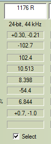
sh*t! I thought I´ve finished my 1176, sounds fine so far BUT I did run it through RMAA and that doesn´t look good at all!
the right channel got a crazy THD value (I was able to reduce this to 2,008 with the dist trimmer, still crazy though)
It got the IC in and hairball EA-11148 out.
could this be a wiring issue or a broken cap or something????


THD Right channel
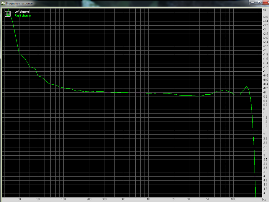
the left channel got OEP in and EA-11148 out. THD is better, not good enough though , BUT look at the Frequency response. whooa!
whats going on there??? is something oscillating? RMAA complained about clipping after the test even if I went in with ike -3db... (got the same problem with my pultec....) Load resistors maybe?
Please help I´m totally lost here! :-(


Frequency Response Left Channel
thanks all!
cheers
martin
the right channel got a crazy THD value (I was able to reduce this to 2,008 with the dist trimmer, still crazy though)
It got the IC in and hairball EA-11148 out.
could this be a wiring issue or a broken cap or something????


THD Right channel
the left channel got OEP in and EA-11148 out. THD is better, not good enough though , BUT look at the Frequency response. whooa!
whats going on there??? is something oscillating? RMAA complained about clipping after the test even if I went in with ike -3db... (got the same problem with my pultec....) Load resistors maybe?
Please help I´m totally lost here! :-(


Frequency Response Left Channel
thanks all!
cheers
martin
gswan
Well-known member
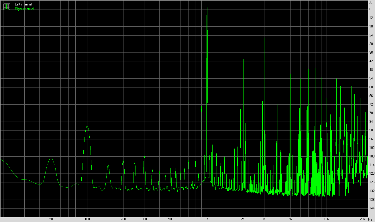
If you are running line frequency of 50Hz then I'd say you have a power supply (AC) noise problem. The frequency plot shows a 50Hz fundamental and then harmonics at 100, 150, 200, 250 ..., which could be components introduced from overdriving sections of the circuit and rectification. Square and triangle waves contain odd harmonics only and rectified sine waves contain even harmonics only.
There's also another 1kHz tone present, also presenting harmonics at 2kHz.
The plot does not show an amplitude scale, so it is hard to see how large these are.
There's also another 1kHz tone present, also presenting harmonics at 2kHz.
The plot does not show an amplitude scale, so it is hard to see how large these are.
gswan
Well-known member
Maybe, if the PSU problem is radiated, not conducted.
gswan
Well-known member
I found the amplitude scale on the RHS. Did you see it?
Looks like a low level PSU noise, look at the scale. According to your plots it is around -120dB?
Can't see any sign of a test signal there though. Check the wiring of the test signal input, and also your output cabling.
Looks like a low level PSU noise, look at the scale. According to your plots it is around -120dB?
Can't see any sign of a test signal there though. Check the wiring of the test signal input, and also your output cabling.
gswan
Well-known member
I don't think so, otherwise the signal would not be at -120dB for one channel and 0dB for the other.
gswan
Well-known member
Why did you use a -120dB signal to test one of them and a 0dB signal to test the other?
gswan
Well-known member
That was not immediately obvious, since the result field names and graphs lacked any labels. I thought it was left and right channel frequency response.
Did you do these measurements with the GR circuit switched out?
Did you do these measurements with the GR circuit switched out?
Similar threads
- Replies
- 206
- Views
- 75K


