All things G1176 - the new "repost" thread.

GroupDIY Audio Forum

Help Support GroupDIY Audio Forum:

This site may earn a commission from merchant affiliate links, including eBay, Amazon, and others.
well I beleive it was al_p that came up with the idea to cut the ground trace perimiter.many thanks for sharing your idea al_p! :sam: :guinness: :thumb:

hi Orson , Did un-linking your XLR's get the last of the hum?

The only way to know which cut gets the quietest result is to A/B/C etc them very critically side by side. (dead quiet audition chain required)

cheers,
Lance
 
Out of curiosity I eliminated the grounded jumper connected between both XLR's with no difference.
I connected the perimeter wire to star ground with no difference either.
Using a computer is not the best way to test for hum :roll: . It's inherent atleast in mine. Increasing mic-pre input gain dramatically lowers G1176 output hiss because it's input volume does not need to be as high. Common sense, I know but I overlooked that before. Just thought I'd share so people know what can and doesn't make a difference in ground loop hum and natural hiss.
I noticed high mic-pre output equals a lower g1176 input setting and a difference in sound. I liked it better when the mic-pre was low and the G1176 input was high. Even though the hiss increases so does something else. It just sounded better, sweeter to my ears. Just my 2 cents. Carry on.
 
hi orson,

You could try the cut I posted on page 20. It may be worth it or may change nothing but I don't think it will make the hum worse.

It would involve jumping pin3 to the pin 4 side and cutting off pin 3 from
the power supply side.

cheers,
Lance
 
OK I will try that manana and then post the results. Isn't there another cut we can make somewhere? I ask this becasue someone made a new PCB design with several different sections of ground trace.
 
http://www.groupdiy.com/index.php?topic=1409

Check the link on the first page by Matthias http://www.geocities.com/m_natsume/1176.html

on his site he proposes a newer design and if you scroll down to around half of the page you can click on a link that will show you a new PCB layout with red tracing the grounds. I know you must have seen this. What I meant before was isn't there another cut we can make BESIDES / IN ADDITION to the ones we already are doing. I don't want to beat this to death but Romeojesus ( Christian) sounds like he has absolutely zero hum. Mine is more like what you describe. BUT I am being anal retentive for sure. Right now I am very happy with the way my G'76 is performing. No doubt!
 
hi Orson,

the reason for me thinking it might be worth trying this one cut first is
that (just before my picture of the cut, stoff followed my written description)stoff reports dead quiet with the cut I suggested and then we had the report of Christians accidental change in the cut.

The hum on my unit is so far down it's more like a ghost of a hum.
When I change my inputs and outputs it does not increase. It's so close to dead quiet that I think if I was using the lundhal tranny it may be gone.
From what you described I think your hum may be stronger?

cheers,
Lance
 
I just found the rev E that mnats did that shows the red perimiter cut beside the input transformer. I think all the rest of the ground is connected.I couldn't find one with 3 cuts.

mnat's new boards (rev F I believe) are gonna be great .But even still I hope we can find a simple solution for this layout. Gyraf, Kev and others
have done so much to get it this far.

cheers,
Lance
 
But even still I hope we can find a simple solution for this layout. Gyraf, Kev and others
have done so much to get it this far.
Agreed. My version isn't meant to be a replacement, just another version with modifications I thought were common and useful. You'll still want Jakob's original board if you want to use the BD517/518 output transistors and the Lundahl wired 2:1.
Check the link on the first page by Matthias http://www.geocities.com/m_natsume/1176.html
Not to toot my own horn or anything but that's my page, not Matthias'. Check the New G1176 design ? thread for progress on the new board and please register your opinions on rotary vs pushbutton switches.
 
[quote author="hitchhiker"] hi Orson,

the reason for me thinking it might be worth trying this one cut first is
that (just before my picture of the cut, stoff followed my written description)stoff reports dead quiet with the cut I suggested and then we had the report of Christians accidental change in the cut.
The hum on my unit is so far down it's more like a ghost of a hum.
When I change my inputs and outputs it does not increase. It's so close to dead quiet that I think if I was using the lundhal tranny it may be gone.
From what you described I think your hum may be stronger?
cheers,
Lance[/quote]

The hum is completely gone. :shock: This unit is now 100% quiet. :shock: THanks for encouraging me to try it. I almost left things ass they were. :green: :thumb: :sam: :guinness:
 
EDIT:

So the current fully-working cut is Hitchhikers cut:

rev_7_cuts.jpg


Is this correct?

Jakob E.
 
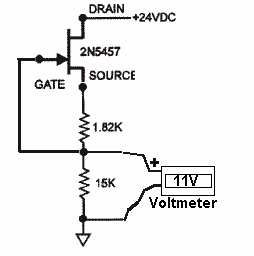
I wanted to mention that I used PRR's jig to match FETs, and it works like a charm - I found two within .01 VDC. Thanks to PRR for that simple and elegant design.
 
[quote author="gyraf"]Seth,
Could you post a link to that?
Jakob E.[/quote]

Jakob,

With pleasure:

PRRFET-sort.gif


I was wondering if higher values are better or what? Most of my matches fell between 6 & 8 volts.

Lance,

Most of my matches were in the same range and I was wondering the same thing. Does anybody know what absolute values would work best?

:thumb: :thumb: :guinness:
 
Would be easy to mount an original urei fet in a contraption like that, to find the ultimate reference value.. unfortunately all our 1176's are racked up and in use for the next month or so..
 
Hi to all :wink: , I have the sifam vumeters now :grin: . But I have problems... I wire the vumeter and now im doing the adjustments. I have some problems with them. The Qvias no problem... but when I try to adjust the tracking pot I can reach the 6dv of gain reduction. I put the signal in adjust the in and out for a unity gain and then i up the input until I have the output at half of input, the vumeter in Gain reduction mode reads only -1 and when i try to turn the track trim its imposible to reach the -6dv...
I dont know why, now im looking components searching errors. ..
Another thing. 0 VU is aprox 0.75 Vrms, arent it?. When I have 0VU on the meter I read something like 1.3 Vrms at output.... is that possible? im very confused with all these.
Oks.. thanks all for that nice Forum :grin:

Arnau
 
Hi Arnau,
Another thing. 0 VU is aprox 0.75 Vrms, arent it?. When I have 0VU on the meter I read something like 1.3 Vrms at output.... is that possible?.
That is normal. The 0 VU is referenced to +4db.

0db=.775V
+4db= 1.23V
The Qvias no problem... but when I try to adjust the tracking pot I can reach the 6dv of gain reduction. I put the signal in adjust the in and out for a unity gain and then i up the input until I have the output at half of input, the vumeter in Gain reduction mode reads only -1 and when i try to turn the track trim its imposible to reach the -6dv...
This adjustment can be tricky, especially when Q1 & Q10 are not well matched in terms of their cutoff voltage.

You have to carefully work the meter track and meter zero trimpots against each other in small steps until things work out. This may include experimenting by starting the adjustment with each trimmer in a different point in rotation relative to the other; that is, start with one full CW and the other full CCW and see if that helps. If not, try the opposite. Sneak up on it.

Dean
 

Latest posts

Back
Top