All things G1176 - the new "repost" thread.

GroupDIY Audio Forum

Help Support GroupDIY Audio Forum:

This site may earn a commission from merchant affiliate links, including eBay, Amazon, and others.
My problem turned out to be a solder bridge and some traces that got lifted when I clumsily desoldered domething. I had the quick impression that one of the ratios was incorrect, but I have to check more carefully. Otherwise it seems to be working great. Thanks to Jakob, Bjorn Zetterlund and all who helped.

:thumb:
 
Thanks, Jakob,

The compressor works great, it's just the meter calibration in GR that's wierd. The meter show 6dB of gain reduction at 1:20, but in the other ratio positions it shows greater reduction instead of less for the same input level. The output levels are correct on the meter and confirmed on my analyzer - as I add ten dB I get the correct amount of output for each ratio. I'm not sure that my generator is putting out 50mv in balanced mode when I'm calibrating. My meter is calibrated in dBm or dBv. Can someone tell me what 50mv is in dBm or dBv? Or, if I'm using a standard DMM am I looking for 50mv across pins 2-3 of the balanced input, or is it from pin 2 or pin 3 to ground? That's where I'm confused. I believe I've seen those calculations around here somewhere, so I'll go search.

Thanks.
 
Seth,

The ratio problem you have has been discussed before here. I don't think it is a problem, but rather a misunderstanding of what the ratio switch does. They alter ratios, yes, but they also change the threshold - so there's no direct comparison between indicated GR and actual ratio. To find actual ratio, you'll have to input different levels, and monitor the output.

77mV is -20dB under 775mV, which is 1mW into 600 Ohms.

Jakob E.
 
Seth

I seem to remember that the threshold point changes depending on the ratio sttting you`re using, so I think what your talking about is normal.

Also most DMM`s does not have a good frequency response & usually only go to about 400Hz with any degree of accuracy (even if they also function asa freq counter) so this may also be the cause of your problem. For these types of measurments you`re better off with a scope or ant A.C millivolt meter.
 
[quote author="gyraf"]Seth,

The ratio problem you have has been discussed before here. I don't think it is a problem, but rather a misunderstanding of what the ratio switch does. They alter ratios, yes, but they also change the threshold - so there's no direct comparison between indicated GR and actual ratio. To find actual ratio, you'll have to input different levels, and monitor the output.

77mV is -20dB under 775mV, which is 1mW into 600 Ohms.

Jakob E.[/quote]

Thanks Jakob and Rob,

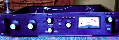
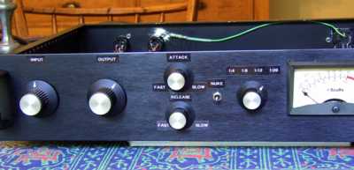
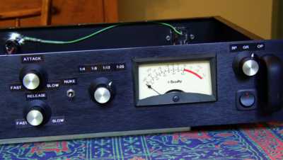
I understand. The output gain metering accurately reflected the selected ratios, but the change in threshold made the GR metering look wrong. So as you say, I misunderstood how the controls interact. That's good to know - I'm much easier to fix. Sounds like it's working fine. Thanks again for all your help. Pix to follow.
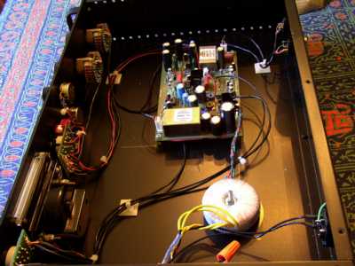
 
Here's some pictures - by happy accident I have a couple of extra channels for my Scully 280. They now have no knobs on them. I decided not to go nuts over the front panel, not now anyway - I'd rather build more stuff. It's definitely functional.

Face.jpg

FaceL.jpg

FaceR.jpg

Inside.jpg


:thumb:
 
I took a look at a real UA 1176 reissue today and noticed the input gain pot is a dual-pot, with two resistors soldered between the two pots and two sets of wires going to the PCB. The markings didn't tell me what ohms they were, but I am curious because here's what I found on comparing mine to the newer real one:

1. My input gain pot is way more sensitive (and touchy) in the lower range than the UA, making me think of trying out a linear pot instead of log.

2. Input thresholds seem lower on my G1176 version, but of course calibration comes into play.


thanks
-kdawg
 
Can anyone who's ordered those sifam AL29's from within UK (farnell right?) gimme the part# for em - seems a few variations they have listed and there aint much to decipher between them...
 
Hey Jakob...

okay then so, from this list:

http://uk.farnell.com/jsp/endecaSearch/searchPage2.jsp?N=1003996+401&Ntk=gensearch_001&Ntt=sifam&Nty=1&specialorder=on&No=0&showImages=true&viewType=&comSearch=true&manufacturerDisplay=true

none of those are the correct vu type right?

this1 frm canford okay?: http://www.canford.co.uk/commerce/productdetails.aspx?productid=58-382

ta
 
[quote author="daArry"]..okay then so, from this list:
http://uk.farnell.com/jsp/endecaSearch/searchPage2.jsp?N=1003996+401&Ntk=gensearch_001&Ntt=sifam&Nty=1&specialorder=on&No=0&showImages=true&viewType=&comSearch=true&manufacturerDisplay=true

none of those are the correct vu type right?[/quote]

Right. They're useable for the SSL, not for 1176. We need a real VU-meter.

this1 frm canford okay?: http://www.canford.co.uk/commerce/productdetails.aspx?productid=58-382
ta

Yes, these are the right ones - they're even much cheaper than what I paid at Farnell...!

Jakob E.
 
hello

- can i use a 1,1K Ohm with 2W in the g1176?
- can i use 220p's instead of the 200p's which are marked on the pcb?


another questio g7 related:


ist it possible to do a chain of resistors : example: 3* 10M + 3* 1M: for a 33M ohm resistor?

thank you very much!
 
great, cheers jakob - will get them later this week :) ordered the lundahls for the outputs from them on monday so cudda got them then...

cant remember when i started this 1176 project but i'm near there! Just got a panel design ready for schaeffer to do the biz too!:

http://notapplicable.co.uk/audiolab/1176/FrontDesign-[1176.jpg

peesh!

:guinness:
 
Just got a panel design ready for schaeffer to do the biz too!:

I don`t want to put a damper on your progress but I just tried to put 2 G1176 in one box with a similar layout to yours. There are a couple of points that I recommend that you check before you place the order, so you don`t f**k it up like I did.

1. Check where you have put the nuke switches. I suspect that the bottom of the meter will be in the way. This is because the meter covers below the level of its fascia behind the panel.

2. Check also that the Ratio & meter switch boards do not touch the nuke switch, the pots, & also the back of the meters. What I found was that the switches project too far back to allow the switch boards to fit in place. You may find that the 2 switch boards will give you more space for the nuke switch if you swap their postions.

I`m going to have to make a completely new front panel through my own stupidity. I just don`t want you to spend a fortune with Schaefer & it doen`t fit.
 
good advice there rob :thumb: I always print out a 1:1 template of any design and chek against the shiz just to be sure normally neways :) thanks!
 
yep. there's a lot of stuff that eats up panel space quickly if you are doing a dual. i'm using giant meters from an MCI tape machine. 3.5" wide, counting the mounting hardware, and just about 3.25" high with the illumination kit. also be aware of lips and flanges that connect your chassis to your panel. i haven't even started the guts yet, just doing metal work and mocking it up to make sure it's all good.
 

Latest posts

Back
Top