All things G1176 - the new "repost" thread.

GroupDIY Audio Forum

Help Support GroupDIY Audio Forum:

This site may earn a commission from merchant affiliate links, including eBay, Amazon, and others.
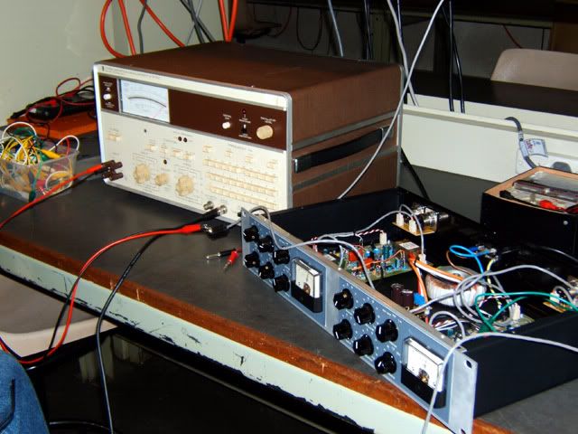
Did the distortion trim on my dualie last night using a Sound Technology 1700B. Gotta love all those interlocking pushbuttons.
dual_1176_dist_trim.jpg

We were able to get the right channel down to 0.08% and the left channel to 0.075% THD. Could be wrong, but I think I read somewhere that if you don't do the trim you should leave the trim pot at the midpoint. Well, with the distortion trimmer turned to nearly the 0 ohm point (clockwise on the G1176 boards) the distortion was lowest; turning it all the way gave only a modest rise in distortion - around 0.1%. At the midpoint distortion was about 0.5%.

Anyone else done the distortion trim? Would be good to compare notes.
 
> one problem is that I used a dual VU meter and it barely moves. set to VU mode it moves a small amount and under much higher levels it moves more..

i have built mine with a sifam meter...my meter does not
move much in vu mode either..(I did the calibration thing)...
in gain reduction mode it works as it should ...

(used the original gyraf board)
 
I have finished all solder work on my first G1176.
I haven't gotten the chassis nor the frontplate for it yet. They should arrive soon.

I'm trying out an alternative meter so note that there could be "something" there.

I have checked and doublechecked for all the usual stuff, component values and orientation, solder blobs, breaks, and that all pots and switches are connected correctly.

I have then powered up and checked that I'm getting the right readings as written on the PCB and the diagram. (Not the more extensive one that Jakob made with readings all over the place. I'm thinking that the rough overview would be sufficient to begin with.)

Then I've connected it to the patchbay, eager to hear the unit in action, but:

1. There is no sound through.

2. The meter acts weird. I noticed this when I first powered up of course. It's a VU meter but first and foremost it acts like it should be connected + to - and - to +. When I switch to GR the needle is glued to the left side of the window while in Bypass and VU mode it returns to the same position as when I turn off the unit.
I've tried to switch polarity on the meter and that gives the expected reaction although it needs serious adjustment somehow. In Bypass and VU mode the needle still sits correctly and in GR mode it now rests at appr. -15 dB (or something. I mainly just focused on the needle moving towards 0dB now).
Note: Regardless of the polarity, in VU mode the needle is "dancing" a little erratic dance. Not very much movement but just enough to look like it's reacting to an outgoing signal, but it doesen't matter whether there's an input or not.

3. How critical is the meter for operating the unit? Will it affect sound at all if it's broken or as in this case (maybe) not the right kind?

I've read the "G1176 : No smoke but then no signal..." thread and will error trace following those directions but I would like to hear if anyone can spot anything with the above description? For instance if it's impossible to make it work if it's not in a case? I mean, the missing common chassis...or something...

Thank you!
 
My G1176 is finally working. Big thanks to nwsoundman for taking the time to have a look at it. For the archives: the problem was that I couldn't set the Bias trim and the GR meter stopped at about -16dB. I replaced the BD518s and that didn't fix the problem. He finally figured out that there are TWO jumper holes marked "18," you use the one depending on the size of your trim pot. One he switched to the other hole (and replaced a blown TL071) the unit started working correctly.

Thanks again to nwsoundman, mnats, Gyraf and everyone else who made this compressor possible. I'll be posting photos soon.

:guinness: :guinness: :thumb:
 
alo
just found something strange.
in the bom,s1 says:2 pole-6 positions.
in the small board,it says:2 pole-4 position.
which one it`s correct?.
best regards
pedro
 
using relays lets you bypass the line amp inside the 1176... so that may or may not be something you want to do.

my experience is that I usually have all my comps on GR mode, rarely use the VU mode.

depending on your input and output level, your VU meter will dance around madly with signal. depends on whether you think this is useful.

one thing however is I set it to VU mode for the ALL switch, so as to not hold the meter pegged...
 
I'm building two 1176's using Mnat's boards and with the OEP transformer on the output only. I finished wiring one and it's passing audio, but when trying to calibrate it, I get a very hot output:

- I'm inputting a 250Hz sine wave at 600mV (tried with a lower voltage too), connected to pin 1 and 2 on the xlr (pin 3 not connected)
- Starting with R81 fully CW, I back it off until I get a 1dB drop in output level with my external meter.
- After this calibration, still in bypass, with the input pot on 8 o'clock and the output pot on 2 o'clock, I get 944mV on the output xlr (pin 1 and 3 tied together)

The unit seems to be working and it's compressing, but the output seems to be way too hot.

However, I just spotted that the supplier sent me some BC108B's instead of BC107B's, so Q3 and Q15 are BC108B and the others BC107B (will change them as soon as I get some new ones). Could this be causing the hot output?
The other trasnistors used are:
Q1, Q10: BF245A
Q6, Q7: BC560C
Q8: BD135
Q9: BD136

/Oscar
 
Jakob:
How do you judge that there's too much?

Actually, I haven't tried it in my studio yet, just with an unbalanced hook up at home (test cd and computer), and it's been years since I used an 1176. But, I figured setting both input and output at unity gain (which normally is about 2 o'clock, right) would output the signal at the same level as it was input (in bypass that is). If the levels are ok as they are, then nobody's happier than me ;)

Still wondering what the BC108B's would do to the signal though.

Thanks

/Oscar
 
I think unity gain is much below 2O'clock - but I don't have a unit around to verify that..

Check for yourself the data sheets for differences between 107's and 108's..

Jakob E.
 
.
Hi all,
Finally finished all the G1176 links, websites etc. Thanks to all who contributed.
Orson for saving the old bits, all who gave calibration info, pioneer trace-cutters, etc..

Haven't started project yet, a few questions:

1. Output transformer: Has anyone used an OT different than OEP or Lundahl? Didn't see any.
Trying to figure pri/sec impedances for alternate trafo spec.
On G1176 schem, with both windings in series:
Lundahl 1540 = 1.22K:1.6K ; OEP 262A2E = 600:2.4K
1K R terminates secondary on G1176 schem.
Also a bit in my notes saying "any 1:1 will work" but didn't footnote it or list author.
Will a 600:600 work for this? (have Triad HS-56V and some other 600:600).

2. Input transformer : From Jakob's site:
The transformer input is an option.
If using the input transformer, ONLY connect point*1 to the input level pot, as the point1 is only for electronically balanced inputs. Actually you could leave the 5532 out, but if it's already there, dont bother to remove it. If using the input transformer, remember to use the inputs marked "Optional trafo input" and not "BAL. INPUT"


So wondering if it's possible to mount all the parts + input trafo, and have separate input jack available for each. Would it be as simple as a switch or relay before the input level pot, switching between point1 and point*1? Can't tell from Jakob's schem. Anyone tried?

3. Planning to try O-12 and others on input, like soundguy posted somewhere, then ran across this in Orson's notes:
Duka: I wanna build G1176 but with 0-12. Can I use this circuit with pot like with Lundahl use or I must use dual pot for "T" atenuator like on original schematics.
No answer in the notes. Missed any other reference to a T-attenuator. I'm assuming a pot is fine, T-atten not needed so long as trafo leads go in the right holes. Correct?

Thanks, Paul
 
Has anybody tried Gssl sidechain filter on the 1176?
Another general question - where do you get good, cheap 19" chassis in UK?
 
just finished reading mnats rotary switch page (thanks!) and I wondered if anybody had a (mouser/digikey) part number for those pins and crimps that he uses to attach the wires to the boards. I may just go ahead and wire directly, but it seems like a nice touch...
Also, what type of switch would be needed and where in the circuit would it go (referring to above post re: switching between xformer and xformerless in put)?
thanks
 
just finished reading mnats rotary switch page (thanks!) and I wondered if anybody had a (mouser/digikey) part number for those pins and crimps that he uses to attach the wires to the boards. I may just go ahead and wire directly, but it seems like a nice touch...
Take a look at the Mill-Max PC Receptacles and PC Pins page in the Mouser catalog. I've bought them from a couple of different sources here but if you go to www.jaycar.com.au and do a search for HP1260 and HP1252 you can get a better idea of what you're looking for...
Also, what type of switch would be needed and where in the circuit would it go (referring to above post re: switching between xformer and xformerless in put)?
If you are just going to switch between the output of the transformer and electronically balanced input circuits, you just need a DPDT switch. I guess the plan above was to tie the input transformer and IC input together and run them in parallel to the input jack?
 
.
I guess the plan above was to tie the input transformer and IC input together and run them in parallel to the input jack?
Nothing real slick. The 2 separate trafo/trafoless inputs to their normal headers, then 1 and *1 to each side of a switch, center of switch to level pot. SPDT would work I think.

It's just to quickly A/B different configs before settling on one, see how it sounds nicest...

I'd guess to use both inputs permanently/practically, calibrating the meter to be worth anything would require matching gain between outputs of trafo/trafoless gain stages, at the pot... so find the trafo you like, then adjust gain-set R of 5532 to 'match'? Overkill for me, and possibly beyond me skills, so will probably just use the one nicest option for the final box.
Also there's couple threads around about T-attenuators, 2:1 step-down function on original 1176 input trafo, etc. Could get complicated with sub trafos.

Love Jakob and Gustav's group-build pics... stacks of snacks.

Paul
 
Nothing real slick. The 2 separate trafo/trafoless inputs to their normal headers, then 1 and *1 to each side of a switch, center of switch to level pot. SPDT would work I think.

It's just to quickly A/B different configs before settling on one, see how it sounds nicest...
Duh. Yeah, SPDT - should know better than to answer posts before that first cup of coffee.

OK, so you're going to use seperate input jacks? I was going to mention that it probably isn't optimum to tie the IC input permanently to the input transfomer primary.
Has anyone used an OT different than OEP or Lundahl? Didn't see any.
Is Kubi around? I think he's been trying out different transformers.
just finished reading mnats rotary switch page (thanks!)
Cool - maybe others can take a look to see if I made any more stupid mistakes: http://www.geocities.com/m_natsume/1176-wiring-rotary.html
 
Back
Top