All things G1176 - the new "repost" thread.

GroupDIY Audio Forum

Help Support GroupDIY Audio Forum:

This site may earn a commission from merchant affiliate links, including eBay, Amazon, and others.
[quote author="gyraf"]Salty,

Page1 in the G1176 layout .pdf has a description on how to mount the pots.

For the resistor in series with the release pot, are you thinking of using a potentiometer with integral switch?[/quote]

Hi Jakob,

I never thought to download the .pdf file! Thanks.

Re. the switched resistor, I will be using a separate switch. Which pin is the correct one to use on the potentiometer?

Many thanks,

Nick Salt
 
Sorry more calibration questions !

If I disconnect the sifam meter I`m using from the circuit so that I can connect it to do the calibration. Can I just put a 3k6 resistor in series with it & strap it across the output ? Its just that if 0dB is is set on the meter to read the wrong level then the FET bias will be wrong.
 
Hi

almost ready for constuction. one question though.
how difficult would it be to adapt the G1176 ratio and meter controls to operate from the original push button switches?
 
Hi Al,

No problem at all, if you can read the schematic, and find the right switches.

Just get the switches, and follow the original schematic..

Jakob E.
 
cool.

thanks Jakob. this has probably been asked before, but whats are the changes you made from the original design besides using the rotary switches?
 
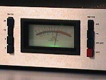
DIY is as much about aesthetics to me as anything so I thought I'd put pushbutton switches on my disco-era silver face clone too. Somewhere in storage I had some interlocking switches but it was too much trouble to excavate them so I just used some cheap non-interlocking ones. Should make the slam mode easy.

I followed Jakob's lead and eliminated the +8 meter setting, putting the G.R. Disable there instead. I can post files if anyone wants - also, if anyone has a source for interlocking switches and can provide me with specs I'd be happy to modify my layout to handle these...
1176_switches_meter.jpg

More images:
Switch PCBs
Mounting Detail
*edited to insert smaller picture
*edited again because I put the wrong picture in
 
ahhh nice job mnats :thumb: . that's what i'm going for. once i get my switches i may ask you for some help. :green:
 
Mnats

Thats neatly done.

I intend to do this, but in the UK its seems difficult to get the right sized buttons to put on the switches.

No problem with the mechanisms

The latching mechanisms are not to difficult to get

RS part no 333-798 for a 4 switch mount and 333-625 for the latching bar (which is supplied in 10 switch lengths).
 
Rob,

Thanks. Check out the RS Australia prices for the switches:
Sold in multiples of 10
stock no. price each
PCB mounting type 10-240 250-990
single 344-647 AUS$ 0.92 AUS$ 0.85
(April 2004 Catalogue page 1032)
Ok, not bad and I need at least 8. Now the latching bar:
Sold in multiples of 5
stock no. price each
5-70 75-245
Latching bar 333-625 AUS$ 6.22 AUS$ 5.79
(April 2004 Catalogue page 1032)
Criminal! 5 latching bars = $31! No thanks. But it helps me understand how they can afford that big office on the main road.

Looks like an easy thing to carve out of a piece of metal though.

Buttons I used are here: http://www.altronics.com.au/cat.asp?cat=4&grp=238&id=H6630
...but they're ID .2mm too large for the RS ones. Damn.
 
hi!

i am stuffing one of gustav´s g1176 pcb boards right now...

and i came across this:

shopping list says: 2x220p polyester

schematic and silkscreening on board say 200p!!

i guess it has got to be 200p´ s right??


one other thing:

one of the bc107b and one of the bc560 transistors and a 1N4003
maybe got a little hot accidentaly while soldering in...

replace on suspicion or go for it??


could´nt get a 500K trim pot!! I guess 470K is ok, is it?


thanks


christian
 
QUOTE:

"200pF/220pF:
Jakob, i think i found a mistake in the part list of the G1176. In the schematic C3 and C4 are 200pf cabs. Also in the pcb layout. Now in the part list i only find 2x 220 pf instead of 2x 200pf
Flo,
Don't worry about that. Both will do fine, and 200pF is not easy to get at all.

Jakob E."


The quote above may be helpful. It was found on Orson Whitfield's site
which you can find in the "META THE 1176 PROJECT"

I would replace components if you feel you have over heated them with a
soldering iron severely. if you are trying to keep costs down and you want to take a chance and see if they are ok that should be fine. It depends on if feel you really toasted them good? I am not exactly sure how sensitive they are to the heat but if you dont feel you've heated them up that much they should be ok. I am not sure how they would affect the rest of the circuit if they were damaged? Sometimes bad components can damage others when you power up the unit. If you have the cash and
dont mind buying the extra components than do it.


The trim pot should be 470K the 500k may be easier to find. Nobody said that the 500K would be a problem so I am presuming it should work fine.


:idea:
 
Yep, 500k can easily be substituted for the 470K pot.

It's because in Europe we use the E3-range for pots (10-22-47) whereas in us and japan you use a 10-25-50-range

Pots are sloppy enough spec'd that these two ranges are essentially the same.

Jakob E.
 
Question about the placement/ orientation of the LORLIN switches
I purchased for the Meter and Ratio for my 1176 project.

I am not sure if anyone has already inquired about this?

I have 2 small pcb's from Gustav. one if for the "Meter" switch
and the other is for the "Ratio" switch.

I noticed the switches are labeled 1-12 (pins)

With the pcb in what I believe the normal orientation/position
how should the switch be orientated/placed in the holes?

Should it be: pin1 on left bottom/ pin 12 right bottom with pin 6
being top center. Or should the switch be placed into the pcb
orientated such as a wall clock with 12 being top center. :?
:?:

Thankyou
 
Thanks Rob!

I have another Question. I have chosen to use The Lundahl
input Transfo rather than the 5532 IC. There are a few other
resistors and such in that circuit. Are there any other components
I can omit other than the 5532 if I will be using the Lundahl
on the input.

Thank you

:wink:
 
Some might remember that I was working on a modified pcb board to try to eliminate the hum problems some people were having with this project without resorting to soldering a ground buss or wire across the board as had been suggested earlier. I also made it so either an OEP or Lundahl input or output transformer could be dropped in and changed it so the Lundahl output is reversed for increased gain and altered the output transistor pads so the BD135/136 could be fitted without twisting the leads.

Well, I'm nearly finished and have most of the wiring done and couldn't resist running a bit of audio through it. It works, it compresses but it's not calibrated yet. I think it's also fairly free of hum.

With the gain reduction disabled and the input and output pots at about 3/4 I ran a recording I made with around 5 seconds of silence then a door closing through my clone and fed the output into my mighty Sound Blaster Live! card.

Mp3 file is 151kB: 1176 test

Sorry, it's not a very scientific test.
 
Great work here Mnats. Is the comp actually in line and recorded in the first 5 seconds or did you just insert 5 secs silence? Reason being, is that I can hear practically nothing at all up until the door slam!! Which is a great thing btw. :0)
 
just a short question:


the 3pos meter switch has an out position...

ist that to bypass the conmpressor, or does it switch the meter off to prevent the slamming of the needle at heavy compression???


mat
 

Latest posts

Back
Top