All things G1176 - the new "repost" thread.

GroupDIY Audio Forum

Help Support GroupDIY Audio Forum:

This site may earn a commission from merchant affiliate links, including eBay, Amazon, and others.
Was there any official solution to units that have a low threshold? Any setting above 48 on the input starts compressing heavily. My voltages all seem to be within reason so I'm going to assume that all is well with the components now.
I see that there were 3 suggestions...
use the original 2N5457
change R26 from 56K to 100K
or install 100K trimmer pot at the input to the

Other than the threshold, these sound great!
Or since I have the 5532 do I exchange the 10K resistor between pins 1 and 2 with the 3.7K resistor?
 
[quote author="dustbro"]Was there any official solution to units that have a low threshold? Any setting above 48 on the input starts compressing heavily. My voltages all seem to be within reason so I'm going to assume that all is well with the components now.[/quote]

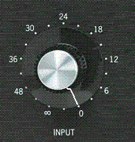
What does '48' mean? Dials can be marked in many ways. Or does this mean -48dBu?

[quote author="dustbro"]
Other than the threshold, these sound great!
Or since I have the 5532 do I exchange the 10K resistor between pins 1 and 2 with the 3.7K resistor?[/quote]

That would be a bad idea. The four resistors R1-B,C,D,E need to be very well matched for good CMRR. Changing this resistor would upset it completely. Read here for more on these resistors: http://www.axtsystems.com/1176clone/inputamp.html

Try measuring a compression curve and plotting it. This will show you the knee characteristics and also the threshold values. I was getting -10 to -15dBu.
 
[quote author="gswan"]
What does '48' mean? Dials can be marked in many ways. [/quote]
48 is the marking at about 8:00 on the dial.
I found this thread about people having too much input gain with the opamp... that's where I got the info from
http://www.groupdiy.com/index.php?topic=14234&start=0&postdays=0&postorder=asc&highlight=100k+trimmer+pot+input
1176knobs.gif

and here is a reply from the master quite a few pages back about the issue
[quote author="gyraf"]This is a bit wierd - my original tests for compatible FET's showed that the BF245A's (at least the three different samples that I got hold on) to be spot-on compared to our Real1176'es.

Could it be sloppy marking, or different manufacturing process messing up? I know too little about real-life FET behaviour to be sure of where this problem comes from..

For now, I don't really know how to get around this - obviously we've run into some non-trivial component tolerances and/or specifications.

A possible simple solution could be to reduce sidechain signal feed level - that will have the same effect as raising the threshold.

We can do this by lowering signal level at the first half of the ratio switch - this part adjusts threshold to match up with different ratios:

Look at the schematic and layout - find R26 - which is 56K - connected to Point15 and the top of the "out level" pot. You will find it on the ratio switch subboard.

If you increase the value of this, you increase the ratio of the voltage divider, and in effect reduce the level going to the rectifier amplifier circuits.

Try with a value of say 100K or 220K in stead of this 56K - or better, try soldering in a 470K trimpot in series with the 56k, which would allow you to find and set a threshold value that suits you. (Maybe it's time for an upgrade of this old-old design - adding a front-panel control for variable threshold? :grin: )

Jakob E.[/quote]
 
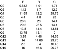
[quote author="dustbro"]new voltages
NEW-VOLTAGES.gif

everything look within reason?
Q6 Q7 Q13 Q15 are a tad off... but close enough?[/quote]

They look close enough.
FYI, here's the simulator output for the GR circuit switched to GR disabled and 20:1 ratio:

Code:
       Vb       Vc     Ve      Ic
Q12   4.56    15.35   3.94    234uA
Q13  15.35    30.00  14.65   5.48mA
Q14   3.49    17.02   2.88    220uA
Q15  17.02    30.00  16.31   6.55mA
 
[quote author="dustbro"]
change R26 from 56K to 100K[/quote]
so I just tried a 220K, and 470K in place of R26. The 470K seems to tame the threshold down a little, but not anywhere close to how my original reacts.
If swapping out R1a is the wrong thing to do, what am I left with?
Gswan, how would I go about measuring a compression curve?
 
Plotting your compression curves is relatively easy. I have an example here that might assist.

You will need a sine wave signal generator and a reasonable level meter (dB or Vrms if you want to do the conversions with a calculator).
1. Set the compressor to GR disable, (attack fully CCW) and release to fully CW.
2. Inject a 0dBu 1kHz sine wave and set the input pot to midway.
note: I measured the input signal using the meter at the input terminals, so I varied the output from the signal generator to perform the measurements. You could use the input control to vary the signal, but you'd need to measure the input signal after this pot (on terminal (2)) instead.
3. Set the output level control so that you measure 0dBu at the output terminals (use your level meter, not the internal meter).
4. Now enable gain reduction and select a ratio - try 4:1 first.
5. Measure the input signal and output signal levels and record them.
6. Adjust the signal generator level and repeat the measurement over a range of input signal levels (say -20dB to +12dB in 3dB steps).
note: My generator output wouldn't go above +2dB, so I started at 0dB and reduced it from there. At -15dB there was no appreciable compression detectable, so I stopped there.
7. Plot the input vs output levels - also include a 1:1 line as a reference.

You can do this for each of the ratios for reference, however I found 4:1 has the softest knee and is usually a good place to start.

To work out the actual ratio, take the most linear part of the gain-reduced curve (usually at the higher signal levels) and calculate the slope (change in input : change in output) between a couple of points on this curve.
 
[quote author="dustbro"]
If swapping out R1a is the wrong thing to do, what am I left with?
[/quote]

You can add a 10K resistor between pin 6 and GND of the 5532 op-amp. This will reduce your input signal level. Alternatively you can drop R1-A to 4K7, as this sets the gain of the summing amplifier.
 
[quote author="gswan"]This will reduce your input signal level. Alternatively you can drop R1-A to 4K7, as this sets the gain of the summing amplifier.[/quote]
Thanks! This worked out pretty well, the threshold is much higher now...but in the process my overall output gain has gone down. Looks like I'll need to do the transformer mod that some people were talking about.
The original transformer was wired 1:2 right? Any diagrams for this mod?
 
Reducing the value of R23 (at the bottom of the voltage divider chain for input signal to the GR rectifier) would also reduce the threshold without affecting the overall gain through the circuit.

You could probably wire a 50K pot inseries with a 10K resistor and have a variable threshold control without upsetting the ratios.

Geoff
 
[quote author="gswan"]Reducing the value of R23 (at the bottom of the voltage divider chain for input signal to the GR rectifier) would also reduce the threshold without affecting the overall gain through the circuit. [/quote]
Good to know. I might try that one too.
so now the transformer is in 1:2... gain is great! unfortunately, now it's time to find the hum. Cutting the suggested traces gets rid of the loud hum, although I'm left with a higher pitch buzz sound that I cant track down. strapping some wire from one side of the board to the other doesnt help.
if it isn't one thing, its another :( bummer
 
It may not be grounding. There are other contributors to mains hum and buzz. Are you using a good power supply or the one on the module?

Check the ESR of your reservoir caps (C24 particularly) if you can and replace if necessary.

Did you also install C* - C*3? These will help with PSU noise problems.
 
Right now I'm using the PSU on the G1176 board and C*-C*3 are installed.
Just for kicks I swapped out C24 with no improvement in buzz. If I crank up both input and output pots, the buzz goes away.
Would you happen to know what's different in the mnats board? Ive had such bad luck with these that I might get the mnats board and swap components just because of the updated grounding scheme.
 
I wasn't sure which boards you were using. I understand that Mako modified the layout to improve the grounding and prevent loops that were present in the original layout, as well as accomodating alternative components in certain places. I'm using a PSU external to the module with very low noise and have no audible noise at all.
 
I picked up a bunch of miniPSU's from sonicwarrior a few months ago
http://www.groupdiy.com/index.php?topic=19418
These would probably work, right? Or am I pretty much safe if I go with the Mnat board?
What a bummer... I was all ready to start smashing audio this weekend.
 
Yes, these are much better PSU's. I have a design for a similar one that I made and use universally for dual supply rails for op-amps. A couple of small mods in resistor values gave me +30/-10 out of it.
psu-5.gif


If C24 didn't change the buzz then it may be a grounding problem. Too many grounds can be as much a problem as too few. It's important to get them in the right place.

For example, if you are using a metal box and you also run grounds to the pot cases then you risk a ground loop. If you connect the shield of the input/output sockets to the case you may also risk a ground loop.

I have heard that there were some PCB mods to isolate a couple of loops (which will be particularly important near sensitive areas like the input balanced amplifier and the signal preamp stages). Also, the more closely matched your input resistors (R1B,C,D,E) the better your CMRR will be. I hand matched them to within 2 ohms.
 
[quote author="gswan"]if you are using a metal box and you also run grounds to the pot cases then you risk a ground loop. If you connect the shield of the input/output sockets to the case you may also risk a ground loop. [/quote]
Right now the ground from my AC connector is going straight to pin 1 of my input. I think that was the recommended way, right?
I had to drop down R1a to get the threshold right, so they are definitely not matched in my unit.
Didn't mnats board take care of the threshold issue too?
 
It's not the way I would do it. The ground from the AC connector is a protective earth. It should go straight to the metal chassis. It should only be connected to the PSU 0V/GND at a single point at the power supply.

This also means that all your input/output connectors should be isolated (signal GND wise) from the chassis. This is usually the case with XLR connectors, where pin 1 (signal GND) is not connected to the metal housing.

I'm not sure about the threshold problem in Mako's boards. I built them up and modified the circuit slightly to get two extra compression ratios that I find useful. I matched the components that were necessary for best performance and had no trouble with calibration or noise. The threshold appears to be around -15dB which is fine by me and performs perfectly.
 

Latest posts

Back
Top