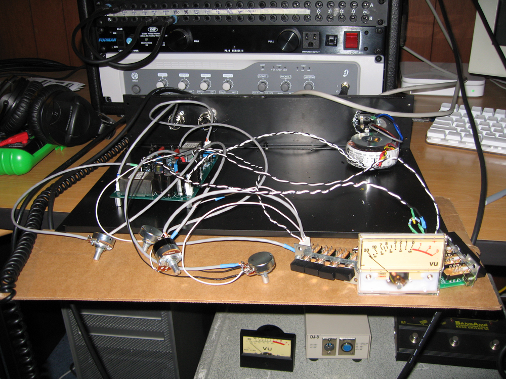
All things G1176 - the new "repost" thread.

GroupDIY Audio Forum

Help Support GroupDIY Audio Forum:

This site may earn a commission from merchant affiliate links, including eBay, Amazon, and others.
Here's a handy piece of software:
http://www.hometheatershack.com/roomeq/

It's intended for use to setup room equalisation in home theatre systems, however running a line in/line out to a piece of equipment will allow you to run a sweep into the unit and measure the output response. Then you can see where, if any, there are abberations in the response curve.
 
Thanks gswan! Handy software indeed. Haven't got it to work on my mac with digicore audio yet. But I have been strapped for time this weekend. I will get it working on a different computer with a proper soundcrd tomorrow I'm sure.

When I originally tested my unit against the rev. D my unit still had some less then desirable wiring. I just ran my tests again, now that it is finished and the wiring is better. My results were a lot better. 3/4 of a db increase at 16K with 10db of reduction. This is basically what the rev.D was doing.

Could have just been shaky wiring.

I am hoping to get room EQ up and running this week and see it charted out though :)

Thanks again!

Mike
 
Having some calibration issues suddenly. Can someone clarify something
for me?

When I send in an input signal (from a function generator) to what input pins should attach the signal? (2+1 or 2+3).

THEN

What pins should I attach my DMM (or scope) to on the output? (2+1 or 2+3)

Really confused about this. Want to get it right.

Thanks again

Mike
 
[quote author="Echo North"]
When I send in an input signal (from a function generator) to what input pins should attach the signal? (2+1 or 2+3).
[/quote]

Pins 2 (hot) and 3 (cold) for a transformer input. For active input short pin 1 (gnd) to pin 3 (cold).

[quote author="Echo North"]
THEN

What pins should I attach my DMM (or scope) to on the output? (2+1 or 2+3)[/quote]

For transformer output pins 2 (hot) and 3 (cold).
 
Thank you again sir!

I need to sit down again tonight and calibrate (3 nights in a row). I actually think my calibration is fine. Every time I calibrate, everything seems fine, trim pots end up in the same place.

My problem is suddenly when I do my ratio tests, they are off. I have calibrated and tested like 12 times and I consistently get:

4 =6.5
8 = 9
12 = 11
20 = 15

Back when my unit looked like this:

2463281848_94272c8f03_o.jpg


I was getting:
4 =5.5
8 = 8
12 = 12
20 = 20

I'll try again tonight. I also need to make sure I'm not getting too close to the knee of the threshold.

Mike
 
Try pushing it a bit harder, with a higher input signal. Remember the ratios are a tangent to the transfer curve (dVo/dVi) so you need to be in the range where the curve is linear. If you are near the compression knee (which is quite soft) then the measured ratio can change quite a lot.

It's also analogue equipment. Don't expect them to be perfect (or even the same between two units). Component tolerances and temperature will have an effect on the settings. Even Qbias will drift around a bit with temperature.
 
uhhhhhg...

not a good night. I started by replacing my 245A fets.(Incase I had a bad one) Then calibrated everything again. Now my ratio's are worse.

4 = 12
8 = 20
12 = 26
20 = 37

I've set my q bias using like 4 different methods and it always ends up in the same spot (except when I switched fets obviously). Would improper q biasing effect compression like this?

I mean it seems my ratios are always fine in respect to each other...they are just too high. I'm measuring from -10 to -5 db's of gain reduction so I should be no where near the soft knee.

Here is a quick test I am doing....do you see a fault in this?

I send in .775 and measure .775 at the output in bypass (unit gain) then turn on gain reduction (ratio of 4 in this case) and get an output of .218 my VU meter shows around -10. (In all instances my VU is tracking fine)

Then I apply .548 (-3) and confirm unity through the in and out in bypass. Turning on gain reduction my out put is now .202.

In bypass my difference is .265 and with a ratio of 4 my difference is .016.

Ratio = 16.6 in this one case (worst one).

Again, my ratios are fine in respect to each other...they are just high.

Mike :(
 
Hmmmm. I don't get the same values as you do for your ratios.
On the 4:1 setting, with your measurements:

1.
Input = 0.775V, 0dB
Output = 0.218V, -11.02dB

2.
Input = 0.548V, -3dB
Output = 0.202V, -11.68dB

Input change (dVi) = 3dB
Output change (dVo) = 0.662dB
Ratio = dVi/dVo = 3/0.662 = 4.53

So for an input change of 3dB, you get an output change of 0.662dB which is a 4.53:1 compression ratio.
 
I've added a spreadsheet (Excel) that helps calculate the ratios from the measurements and draws the little graph.

http://www.axtsystems.com/index.php?view=article&catid=34%3A1176ln&id=54%3A1176lnratios&option=com_content&Itemid=27
-Geoff
 
I may be the least intelligent person on the planet earth. Maybe I should win an award :)

I see now I was trying to be cleaver by just removing the db's from the equation and just look at voltage ratios. Looking at your post, I now see that voltage to db relationship is not linear (not sure if that's the right word). That is why increasing the compression to avoid the soft knee made my calculations worse. (I think that makes sense)

Either way my problem was that I was not converting the output voltage back to decibels.

Everything is fine with my unit. Again, this is the third "problem" I have had since I finished the build that turned out not to even be a problem.

Thanks again Geoff. You're help has been invaluable.

Mike
 
All done!

One question:

Is it normal for the release knob to effect the meter with no gain reduction or in bypass. It's only about 1/16 of a db.

-Release knob at 12 O'clock..meter dead center on zero.
-Release knob fully ccw..meter just slightly ccw of zero.
-Release knob fully cw..meter just slightly cw of zero.

Normal?

Mike
 
Any reason why the NPN's have to be BC107 ?
If I have other generic NPN's with similar spec would that be OK?
Such as 2N5088 / 2N4401 / BC109 etc ... which I have dozens of.
Ta,
MM.
 
Another question in the Lab got me wondering about my G1176.
It works and sounds great but the meter sometimes will not move from the far left unless you tap on it. Every now and then through continous use it will stop working again. So I tap on it again and it will work for a little while. The meter also doesn't calibrate well. When I set it to zero (on the meter) using the trimmer on the pcb it never goes back to the same point (close but not the same point)
I'm using the Sifam vu meter.
Any ideas?
 
Could be a faulty/sticky meter, like the fuel gauges in aircraft in the movies ...
Otherwise you could have a bad solder joint, depending on where/how you tap.

Is it mechanical, electrical or a combination of both?
 
I think its just mechanical.
I just tap on the face of the meter while its in the rack and it starts moving again.
Are there adjustments on the meter to fix things like that?
 
Find out where it's sticking.
The needle might be bent and is touching the surface of the decal, or the decal may have warped. Otherwise there may be problems near the meter coil and return spring. You need to have a close look at it.
 
i am nearly finished my dual 1176. after calibrating the unit i found out
a strange thing with the meter in GR mode:

when i switch from higher ratio to lower ratio the meter in GR mode goes for a short time to the righter end-position and then back to zero.
its all the same in all switching position (20 to 12, 12 to 8 and 8 to 4)

in the other way from lower to higher ratio the meter goes for a short time
to the lefter position and then back to zero.
again in all switching positions (4 to 8, 8 to 12 and 12 to 20).

for information, i have the mnats rev. j board, with rotary switches and the all modus realized with the switch from mnats.

does anybody have the same behavior?
i would be nice when people with finished units make a short test to see
if he have the same behavior...
 

Latest posts

Back
Top