I used UA pushbuttons and I have the same behavior. Not all the way left or right...but bounces briefly right or left depending on the direction of the ratio (like you described)
Just had a look at my unit and it does flick the GR meters when the ratios are changed. Never noticed it before, doesn't appear to affect the sound.
I can only put it down to the step change in offset bias from the ratio switches to the juncrion of R74/R75, although I would have thought that C21 was large enough to dampen this effect. I'll pop the CRO on it next time I get the chance and see what's happening.
I have built two dual 1176 compressors from Mnats rev J boards. One is working fine, the other one needs attention. Could someone please email or direct me to a hi rez picture of Mnats rev J board unstuffed. I need to identify component numbers for trouble shooting purposes & most components obscure the silk screened legend on the circuit board.
[quote author="jrfred453"]Another question in the Lab got me wondering about my G1176.
It works and sounds great but the meter sometimes will not move from the far left unless you tap on it. Every now and then through continous use it will stop working again. So I tap on it again and it will work for a little while. The meter also doesn't calibrate well. When I set it to zero (on the meter) using the trimmer on the pcb it never goes back to the same point (close but not the same point)
I'm using the Sifam vu meter.
Any ideas?[/quote]
I have this with my original UA as well... nothing I lose sleep about...
[quote author="bluesman714"]Could someone please email or direct me to a hi rez picture of Mnats rev J board unstuffed. I need to identify component numbers for trouble shooting purposes & most components obscure the silk screened legend on the circuit board.
[/quote]
This might help:
http://www.axtsystems.com/index.php?view=article&catid=34%3A1176ln&id=50%3A1176lnmodule&option=com_content&Itemid=62
Finally found some time to work on this. Setting up a test tone at the input (transformer in/out setup) I hear output. Using a scope I get no signal at the top of the input pot. I went back to scope the transformer and I get signal at pins S s F and f on the primary side, nothing on the sec side.
From readin the meta I gathered that the tranny setup should be setup 2:1 on input and 1:2 on output for best overall signal level. I believe I have the trannie wired correctly. according to Mnats, there is one link you must add, which I've done and one trace to cut which I've also done. This actually worked fine before (I had signal at top of input pot) so I'm guessing an intermittent connection somewhere. although I'm not sure where.
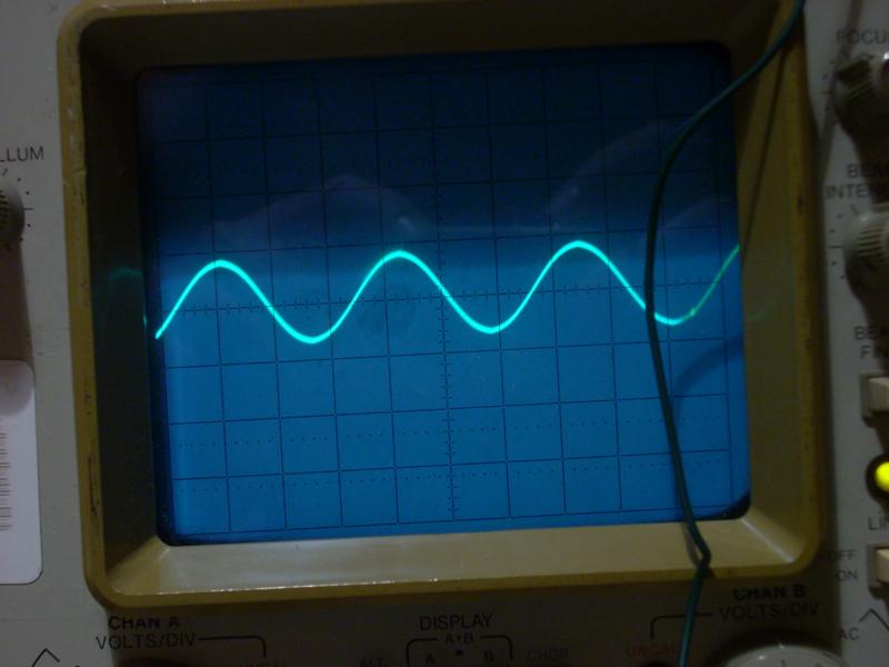
OK, using 2 and 3 now it works (my test cable was shorted out). Now things look good at the trannie. Middle terminal on input pot has signal; none when fully CCW and then nice looking sine wave at full. Looks like this at full CW input pot:
Have signal at the terminal to it's right when looking from the front. Looks the same as the above signal. Doesn't chane with rotation of input pot. FWIW, Q1 has been removed for testing.
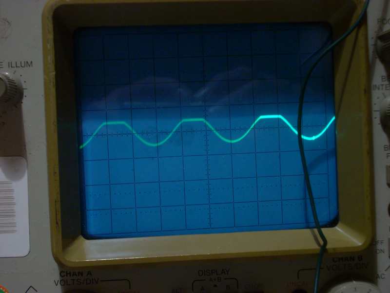
Looking at Q2. Excuse my ignorance on the pin #s if they are wrong. Pin 2 looks like this :
Pins 1 and 3 look like a small square wave. Need more info?
Would be nice to know the vertical scale of your scope for these pictures. Otherwise they mean very little.
Q2 has 3 terminals. B, C and E. Calling them pin 1, 2, 3 is of no value.
First check your DC bias values, particularly around Q2 since this looks like the top is clipping (check values of R11 and R12).
I believe I'm at 5v / msec. 1-Em 2-base and 3 col Data sheets are vague on this (at least mine is) I think they show from underneath. It looks like the base on Q2 is what is showing the waveform with the chopped top and the other two, Em and Col are showing the square wave just in opposite phase; col shows peaks down and em shows peaks up.
I assume I'll need to unsolder any resistors from the board in order to test?
That would be 5V/div (on the vertical scale setting), and maybe 1ms/div on the horizontal scale setting? Are you using a 1x or a 10x probe?
To check the resistors you can read the codes first to see if they are correct. If you still suspect them or are unsure then to test them properly you will need to lift one leg of the resistor.
Normally they have a little marking on them that say 'x1' or 'x10' and some have a switch to select the x1 or x10 setting. We'll assume for now that it's a x1 probe. In which case you are feeding an 8Vp-p signal into the unit, which seems quite high for testing.
How are your DC bias voltages around Q2 with no input signal?
The voltages look OK. Thanks for the heads up about the site, it seemed to have happened overnight. It should be OK now.
Set your input to something lower, say 2.2Vp-p (that's 0.775Vrms). Now run the scope over the signals and check that they are OK through the amplifier. Measure the gain of each amplifying section to confirm that it's all OK.


![Soldering Iron Kit, 120W LED Digital Advanced Solder Iron Soldering Gun kit, 110V Welding Tools, Smart Temperature Control [356℉-932℉], Extra 5pcs Tips, Auto Sleep, Temp Calibration, Orange](https://m.media-amazon.com/images/I/51sFKu9SdeL._SL500_.jpg)


